20
Ensure that all protecti ons removed
for the electric connection have been
restored before powering the unit
electrically.
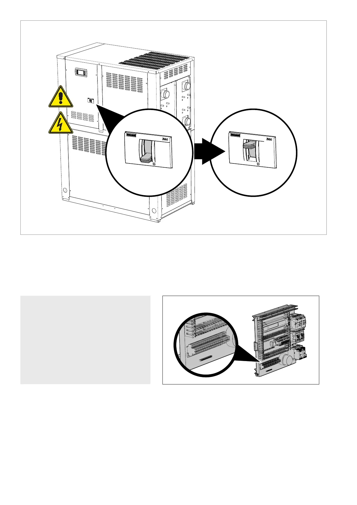
Position the system master switch
(outside the appliance) at “ON”.
System master switch (ON/OFF)
ONOFF
Key:
the auxiliary control board points indicated are the ones
that the installer can use.
0/1 Remote ON/OFF
FL Evaporator ow switch
FLH Condenser ow switch
EMF Multi-purpose input (just the enabling)
• chiller power limiting
• setpoint (heating/cooling) variation
ATTENTION: for connect 0/1, FL, FLH, EMF use the auxiliary control board and refer to the complete electric diagram on the machine.
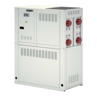
CONNECTING THE AUXILIARY CONTROL BOARD
Position of the auxiliary control board on the electrical panel