13
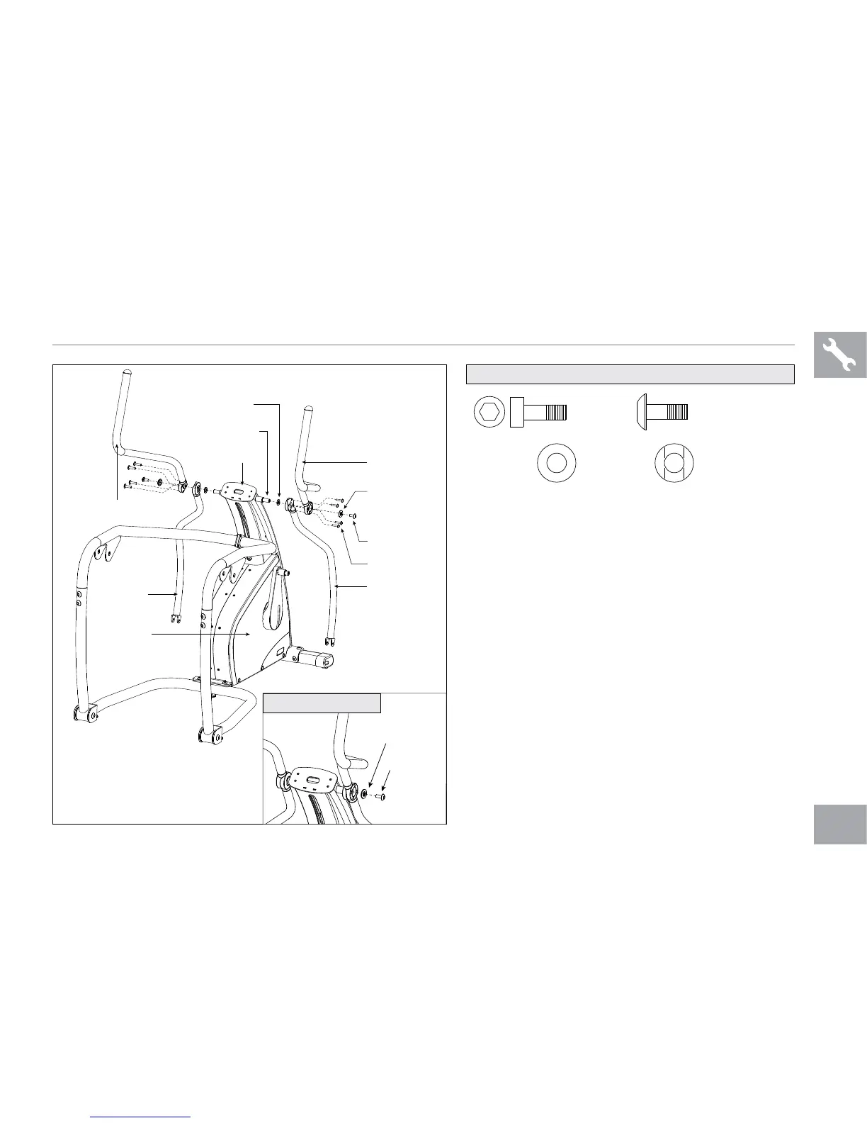
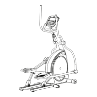
ASSEMBLY STEP 4
A Open HARDWARE FOR STEP 4.
B Slide 1 WAVY WASHER (J) onto each HANDLEBAR
SHAFT.
C Slide the LEFT LOWER HANDLEBAR onto the
HANDLEBAR SHAFT. Be sure the LEFT LOWER
HANDLEBAR is positioned the same as shown in the
diagram.
D Slide the LEFT UPPER HANDLEBAR onto the
HANDLEBAR SHAFT. Using 4 BOLTS (H) connect
the UPPER AND LOWER HANDLEBARS as shown
in the diagram. Do not tighten any bolts until all 4 are
started.
E Secure the HANDLEBAR ASSEMBLY using 1
WASHER (I) and 1 BOLT (C). NOTE: be sure to
attach WASHER (I) as shown in STEP E diagram.
F Repeat steps B–E on the opposite side.
BOLT (H)
20 mm
Qty: 8
WASHER (I)
34 mm
Qty: 2
BOLT (C)
16 mm
Qty: 2
WAVY WASHER (J)
23 mm
Qty: 2
HARDWARE FOR STEP 4:
BOLTS (H)
BOLT (C)
WASHER (I)
MAIN FRAME
RIGHT UPPER
HANDLEBAR
LEFT UPPER
HANDLEBAR
REAR MAST COVER
HANDLEBAR SHAFT
WAVY WASHER (J)
LEFT LOWER
HANDLEBAR
RIGHT LOWER
HANDLEBAR