15
12. Location
Refer to Fig. 12.3 or Fig. 12.4
The location chosen for the appliance must permit
installation and the provision of a satisfactory ue and an
adequate air supply. The location must also provide adequate
space for servicing and air circulation around the appliance.
Oil supply
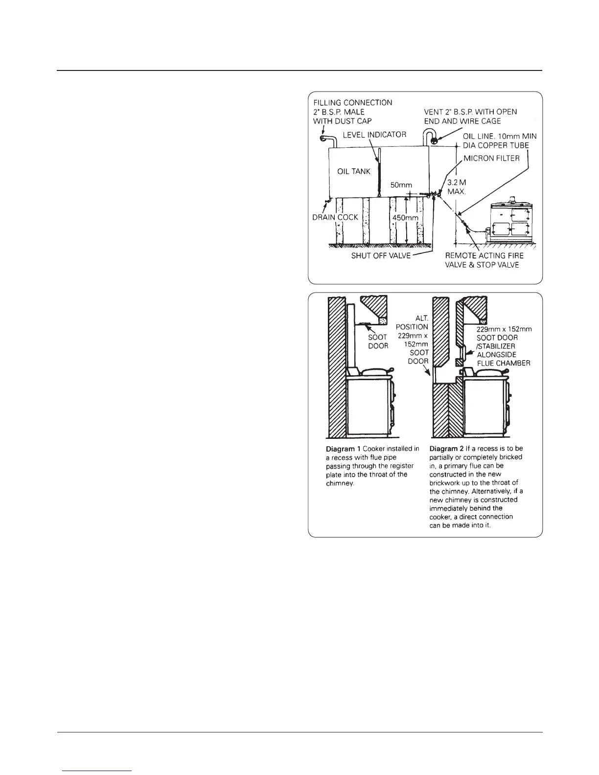
Oil Storage - See Fig. 12.1 Oil Storage Tank and Pipeline
details.
The recommended oil tank size is 1400 litres (300 gallons)
minimum, and the Codes of Practice governing its installation
are covered by BS 5410.
The requirements for mild steel tanks should be to BS 799:
Part 5 and advice should be sought from the manufacturers
for the installation of Plastic Oil Tanks as an alternative
consideration.
The oil storage tank must be positioned with the bottom of
the tank not less than 450mm, and the top not more than
3.2m above the base of the cooker.
Oil Pipe Line
The oil line from the storage tank to the appliance should be
tted with a remote acting re valve (such as a Teddington
KBB-66°C) located outside the building, or where the supply
enters the wall on the inside of the building and with the heat
sensing phial of the re valve, located as near as practicable
on the valve side of the cooker.
A 5-10 micron oil lter should also be tted in the oil line, and
the minimum size of the copper oil pipe line should not be
less than 10mm diameter.
A stop valve must be tted near the appliance, in an
accessible position.
Oil Control Valve
Oil is metered to the oil burner and controlled by a constant
level oil valve, complete with a low voltage Electric Top, which
is electrically activated by the cooker thermostat to maintain
the optimum oil rate and heat input.
A remote acting re valve is located adjacent to the oil control
valve on the inlet side, with the sensing phial located behind
the outer burner door.
The oil control valve can be bolted on either left-hand or
right-hand side of the cooker, or at some other convenient
position adjacent to the cooker and in the same room as the
cooker, by the Authorised AGA Distributor who will connect
up to the burner. If the control valve is tted away from the
cooker, the oil line between the valve and cooker must not
exceed 1m in length. The connection for the oil line to the
control valve is ¼in in B.S.P.
Fig. 12.1 Oil Storage Tank and Pipeline details
Fig. 12.2 Flue Layouts