74 Troubleshooting
List of Required Tools
a. lPT and 2PT Pozidriv screwdrivers.
b. Tl0, T15 and T25 Torx screwdrivers.
c. Allen wrench, 0.050 inch.
d. Hex driver, 7 mm.
e. Long nose pliers.
f. Antistatic wrist discharge strap.
Top Cover, Removal & Replacement
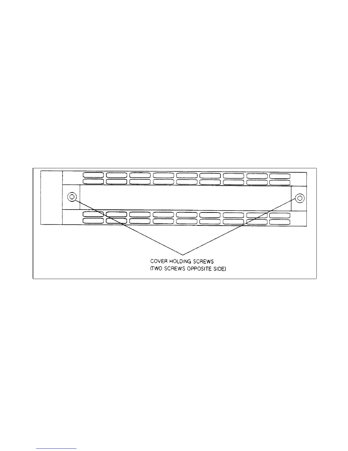
a. Using a T25 Torx screwdriver, unscrew the two screws which hold the carrying straps to the power supply, and then
remove the other two screws from the opposite side of the case.
b. To remove the cover, you must first spread the bottom rear of the cover and then push the cover back to disengage it
from the front panel.
c. Slide the cover backward until it clears the rear of the power supply.
Figure 3-19. Location of Carrying Strap Restraining Screws, Power Supply Side View
A2 GPIB Board, Removal & Replacement (for 664xA & 665xA Models Only)
To remove the GPIB board, proceed as follows:
a. Remove the top cover of the power supply as described under, "Top Cover Removal and Replacement ."
b. At the rear of the-power supply, remove the protective standoff piece (directly above the AC power receptacle).
c. Remove the two (2) 7 mm, hex screws that hold the GPIB connector in place.
d. At the rear of the supply, remove the two (2) screws that hold the HB-IB board to the chassis .
e. From the top of the power supply, disconnect the phone cable at connector J107 on the GPIB board (the other end of
this cable goes to the main board).
f. Disconnect the phone cable at connector J108 on the GPIB board (the other end of this cable goes to the front panel
board).
g. Disconnect connector P101 on the GPIB board (the other end of this cable goes to the transformer secondary).
h. Remove the GPIB board from the power supply by gently pulling back on the metal holding clip that holds the front
end of the GPIB board in place.
i. To reinstall the GPIB board, perform the above steps in reverse order.
 Loading...


