f. Record the value displayed on the controller. This
value should be within the DVM reading noted in
step d and the limits specified below.]
g. Program the selected output’s voltage to the Low
Range Full Scale value (7 V for 25W or 16 V for
50W outputs) by sending the following string:
VSET <ch>, <7 or 16>
h. Record the output voltage readings on the DVM
and the front panel display. The readings should be
within the limits specified below for the particular
output type tested.
i. Run the program listed in step e. Record the value
displayed bye the controller. This value should be
within the limits specified below.
j. Select the high voltage range using the range
command:
VSET <ch>, 50
Or Press range and volt buttons
k. Program the selected output channel to zero volts
by sending the string:
VSET <ch>, 0
l. Record the output voltage readings on the digital
voltmeter (DVM) and the front panel display. The
readings should be within the limits specified
below. Also, note that the display indicates the
output current and the CV, RMT, and ADDR
annunciators are on. Note that the output current
reading is approximately zero because there is no
load connected.
m. Read back the output voltage from the selected
channel over the GPIB by running the program
from step e.
n. Record the value displayed on the controller. This
value should be within the DVM reading noted in
step 1 ± 10 mV.
o. Program the selected output’s voltage to 50 V by
sending the following string:
VSET <ch>, 50
p. Record the output voltage readings on the DVM
and the front panel display. The readings should be
within the limits specified below.
q. Run the program listed in step e. Record the value
displayed bye the controller. This value should be
within the DVM reading ± 18 mV.
r. Repeat steps a through q for each output present in
your supply.
3-13 CV Load Effect. This test measures the change in
output voltage resulting from a change in output
current from full to no load.
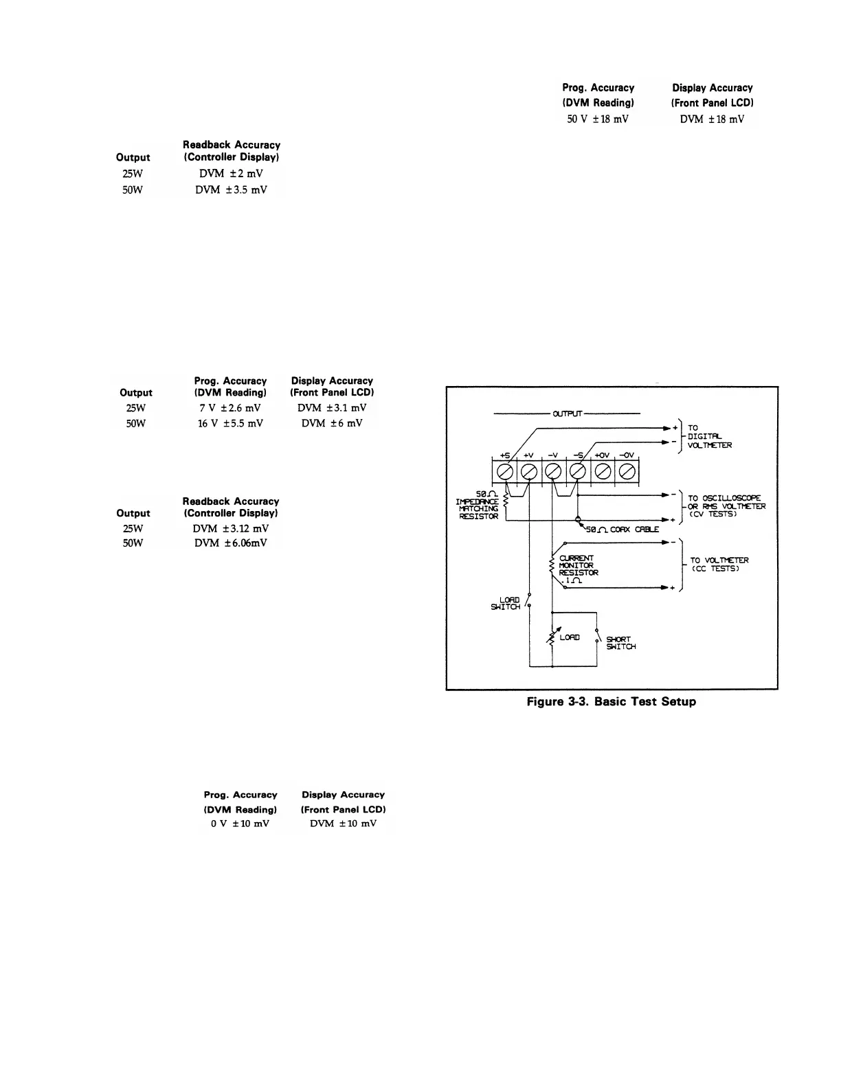
a. Turn off the supply and connect the output to be
tested as shown in Figure 3-3 with the DVM
connected between the + S and – S terminals, the
Load switch closed, and the Short switch opened.
↑
b. Turn on the supply and select the output to be
tested (OUTPUT SELECT key on front panel).
c. Program the current of the selected channel to the
values below by sending the following strings:
25W ISET <ch>, 0.515
VSET <ch>, 50
50W ISET <ch>, 1.03
VSET <ch>, 50
d. Adjust the load for 0.5 Amp (25W) or 1 Amp (50W)
as indicated on the front panel display. The CV
annunciator on the front panel must be on. If it is
not, adjust the load down slightly.
e. Record the output voltage reading on the DVM
connected to + S and – S.
f. Open the Load switch and again record the DVM
voltage reading. The difference between the DVM
readings in steps e and f is the load effect voltage
and should not exceed 0.5 mV.
3-5
Artisan Scientific - Quality Instrumentation ... Guaranteed | (888) 88-SOURCE | www.artisan-scientific.com

 Loading...


