g. Repeat steps a through f for each output in your
supply.
3-14 CV Source Effect. This test measures the change
in output voltage that results from a change in ac line
voltage from the minimum to maximum value within
the line voltage specifications.
a. Turn off the supply and connect the ac power line
through a variable voltage transformer.
b. Connect the output to be tested as shown in Figure
3-3 with the DVM connected between the + S and –
S terminals, the Load switch closed, and the Short
switch opened.
c. Adjust the transformer to 13% below the nominal
line voltage.
d. Turn on the supply and select et output to be tested
(OUTPUT SELECT key on the front panel).
e. Program the current and voltage of the selected
output to the value below by sending the following
strings:
ISET <ch>, <0.515(25W) or 1.03(50W)>
VSET <ch>, <50>
f. Adjust the load for 0.5 A (25W) or 1 A (50W) as
indicated on the front panel display. The CV
annunciator on the front panel must be on. If it is
not, adjust the load down slightly.
g. Record the output voltage reading on the DVM.
h. Adjust the transformer to 6% above the nominal
line voltage.
i. Record the output voltage reading on the DVM.
The difference between the DVM readings in steps
g and i is the source effect voltage and should not
exceed 0.5 mV.
j. Repeat steps b through I for each output in your
supply. Be sure to turn off supply before
performing step b.
3-15 CV Noise (PARD). Periodic and random deviations
(PARD) in the output (ripple and noise) combine to produce
a residual ac voltage superimposed on the dc output voltage.
CV PARD is specified as the rms or peak-to-peak output
voltage in a frequency range from 20 Hz to 20 MHz. This test
measures the rms and peak-to-peak noise on the output.
a. Turn off the supply and connect the output to be
tested as shown in Figure 3-3 to an oscilloscope (ac
coupled) between the + S and – S terminals, the
Load switch closed, and the Short switch opened.
Be sure to keep the leads from the 50 ohm coaxial
cable shield that run to the + S and – S terminals as
short as possible to avoid external noise pickup.
b. Turn on the supply and select the output to be
tested (OUTPUT SELECT key on the front panel).
c. Program the current and output voltage to the
values below:
ISET <ch>, <0.515(25W) or 1.03(50W) >
VSET <ch>, 50
d. Adjust the load for 0.5 or 1 Amp as indicated on the
front panel display. The CV annunciaor on the front
panel must be on. If it is not, adjust the load down
slightly.
e. Note that the waveform on the oscilloscope should
not exceed 3 mV peak to peak.
f. Disconnect the oscilloscope and connect an rms
voltmeter in its place. The rms voltage reading
should not exceed 500 µV.
g. Repeat steps a through f for each output in your
supply.
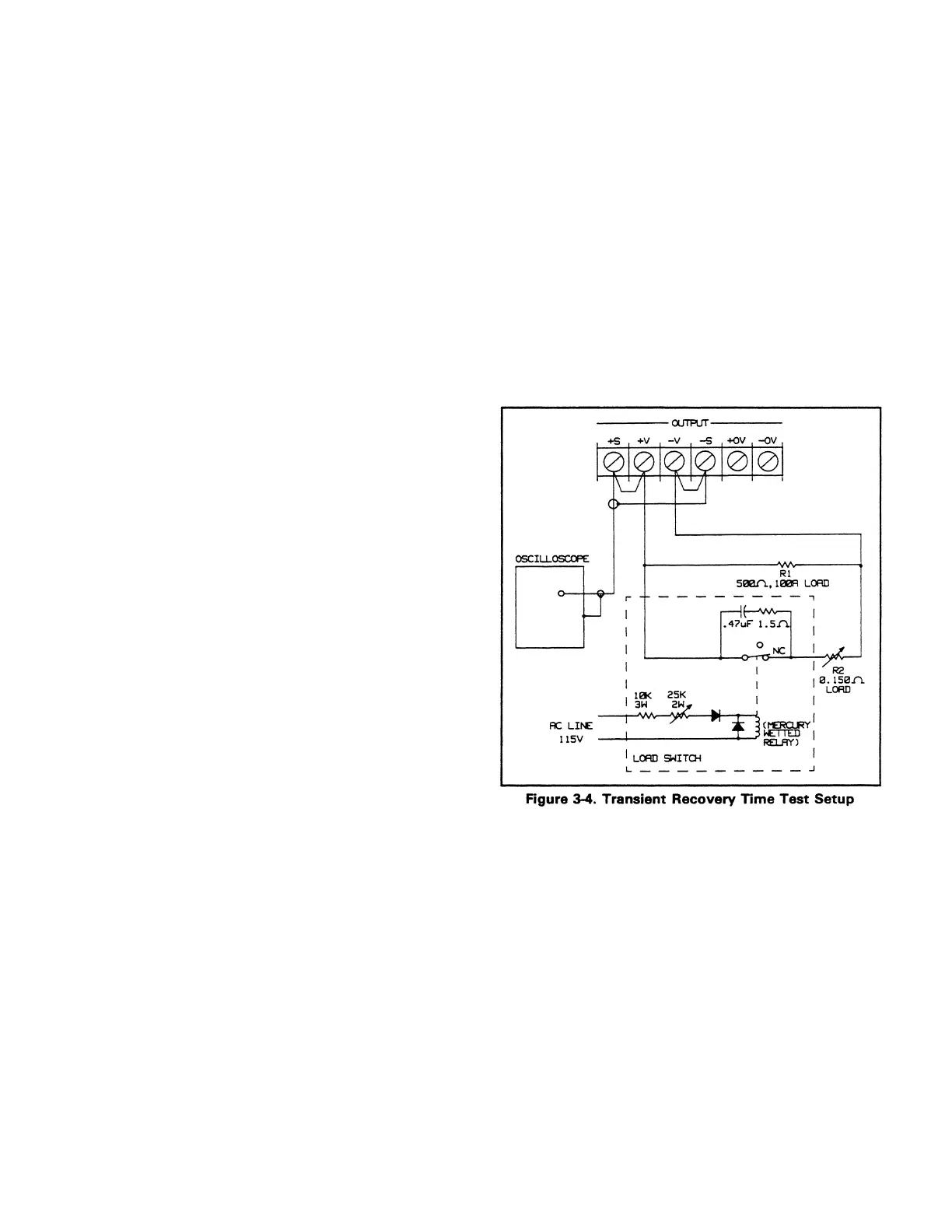
3-16 Transient Recovery Time. This test measures the time
for the output voltage to recover to within 75 mV following
a change from 100 mA to 0.5 Amp(25W) or 1 Amp(50W).
a. Turn off the supply and connect the output to be
tested as shown in Figure 3-4.
b. Turn on the supply and select the output to be
tested (OUTPUT SELECT key on the front panel).
c. Program the selected output’s voltage to 50 V and
the current to 0.515(25W) or 1.03(50W).
d. With R2 disconnected, connect R1 and ensure the
output is 100 mA as indicate on the front panel
display.
e. Connect R2 and adjust the output to read 0.5
Amp(25W) or 1Amp(50W) on the front panel
display. Note that the CV annunciator should be
on. If it is not on, readjust R2 until it is on.
3-6
Artisan Scientific - Quality Instrumentation ... Guaranteed | (888) 88-SOURCE | www.artisan-scientific.com

 Loading...


