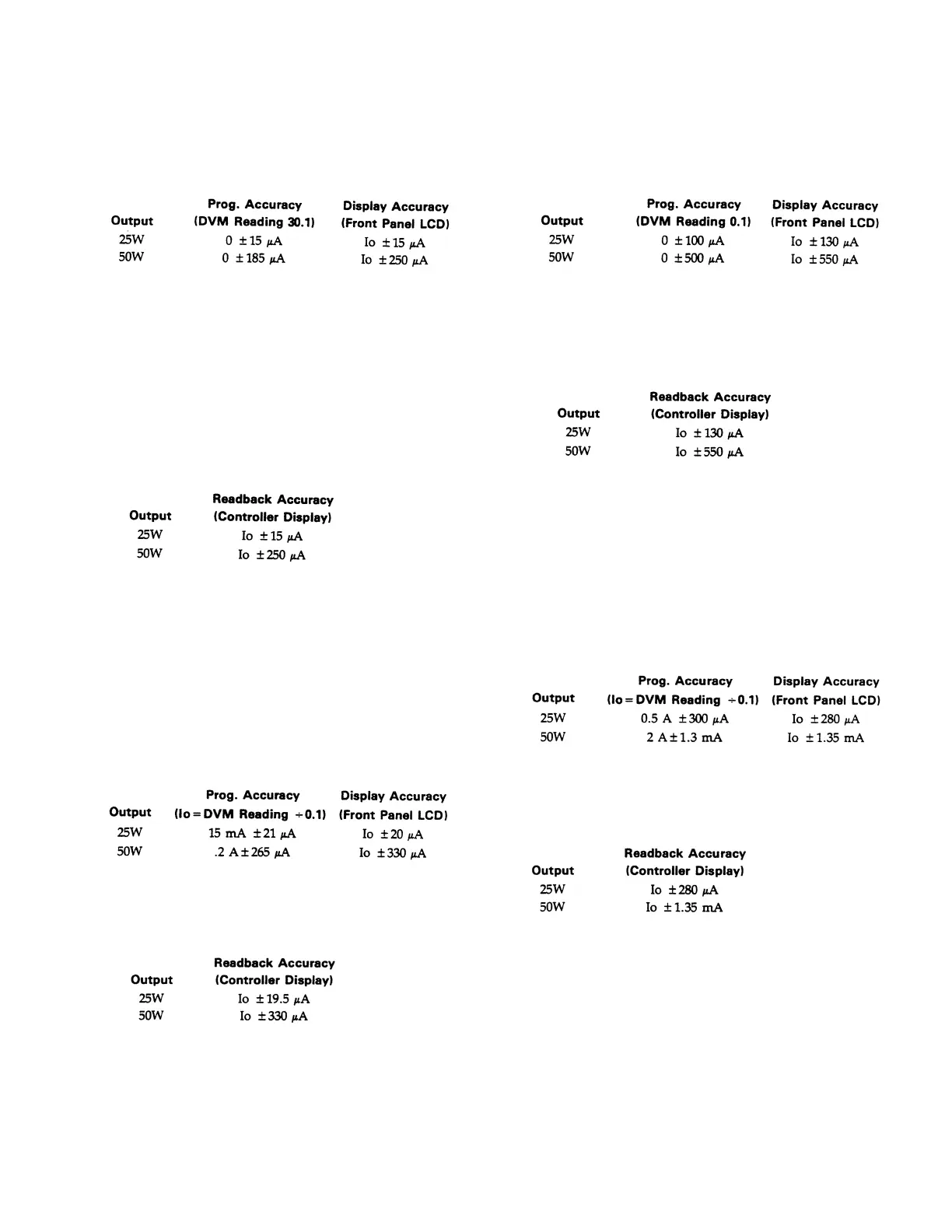
d. Divide the voltage drop across the current
monitoring resistor by the value 0.1 to convert to
amps and record this value (Io). Note also the
current reading on the front panel display. The
readings should be within the limits specified
below for the particular output type being tested.
e. Read back the output current from the selected
channel over the GPIB to the controller by running
the following program:
10 OUTPUT 750; “IOUT? <ch>
20 ENTER 705; A
30 DISP A
40 END
f. Record the value displayed on the controller. This
value should be within the limits specified below
using the Io reading noted in step d.
g. Program the selected output’s voltage to 5 V and
the current to the Low Range Full Scale Current
value by sending the strings:
VSET <ch>, 5
ISET <ch>, <.015(25W) or .2(50W)>
h. Divide the voltage drop across the current
monitoring resistor by the value (0.1) to convert to
amps. Record this value (Io). Note also the current
reading on the front panel display. The readings
should be within the limits specified below for the
particular output type being tested.
i. Run the program listed in step e. Record the value
displayed by the controller. This value should be
within the limits specified below using the Io
reading noted in step h.
j. Select the high current range and program the
voltage to 5 volts and the current to zero by
sending the following strings:
IRSET <ch>, <0.5(25W) or 2(50W)>
VSET <ch>, 5
ISET <ch>, 0
k. Divide the voltage drop across the current
monitoring resistor by the value 0.1 to convert to
amps and record this value (Io). Note also the
current reading on the front panel display. The
readings should be within the limits specified
below for the particular output type being tested.
l. Read back the output current from the selected
channel over the GPIB to the controller by running
the program in step e.
m. Record the value displayed on the controller. This
value should be within the limits specified below
using the Io reading noted in step k.
n. Program the selected output's voltage to 5 V and
the current to the High Range Full Scale Current
value by sending the strings:
VSET <ch>, 5
ISET <ch>, <0.5(25W) or 2(50W)>
o. Divide the voltage drop across the current
monitoring resistor by the value (0.1) to convert to
amps. Record this value (Io). Note also the current
reading on the front panel display. The readings
should be within the limits specified below for the
particular output type being tested.
p. Run the program listed in step e. Record the value
displayed by the controller. This value should be
within the limits specified below using the Io
reading noted in step h.
q. Repeat steps a through p for each output in your
supply.
3-22 Negative Constant Current ( - CC) Operation.
This test verifies the readback and display are accurate
when the output is in negative current limit operation. It
also checks that the negative current limit of the 50 watt
outputs have two different values depending upon the
output voltage.
a. Turn off the supply and connect the output to be
tested as shown in Figure 3-6.
3-8
Artisan Scientific - Quality Instrumentation ... Guaranteed | (888) 88-SOURCE | www.artisan-scientific.com

 Loading...


