b. Set the external power supply to 5V and its current
limit to .75 amps for a 25 watt output or 3 amps for
a 50 watt output.
c. Turn on the supply and select the output to be
tested (OUTPUT SELECT key on the front panel).
d. Program the selected output channel to OV by
sending the string:
VSET <ch>, 0
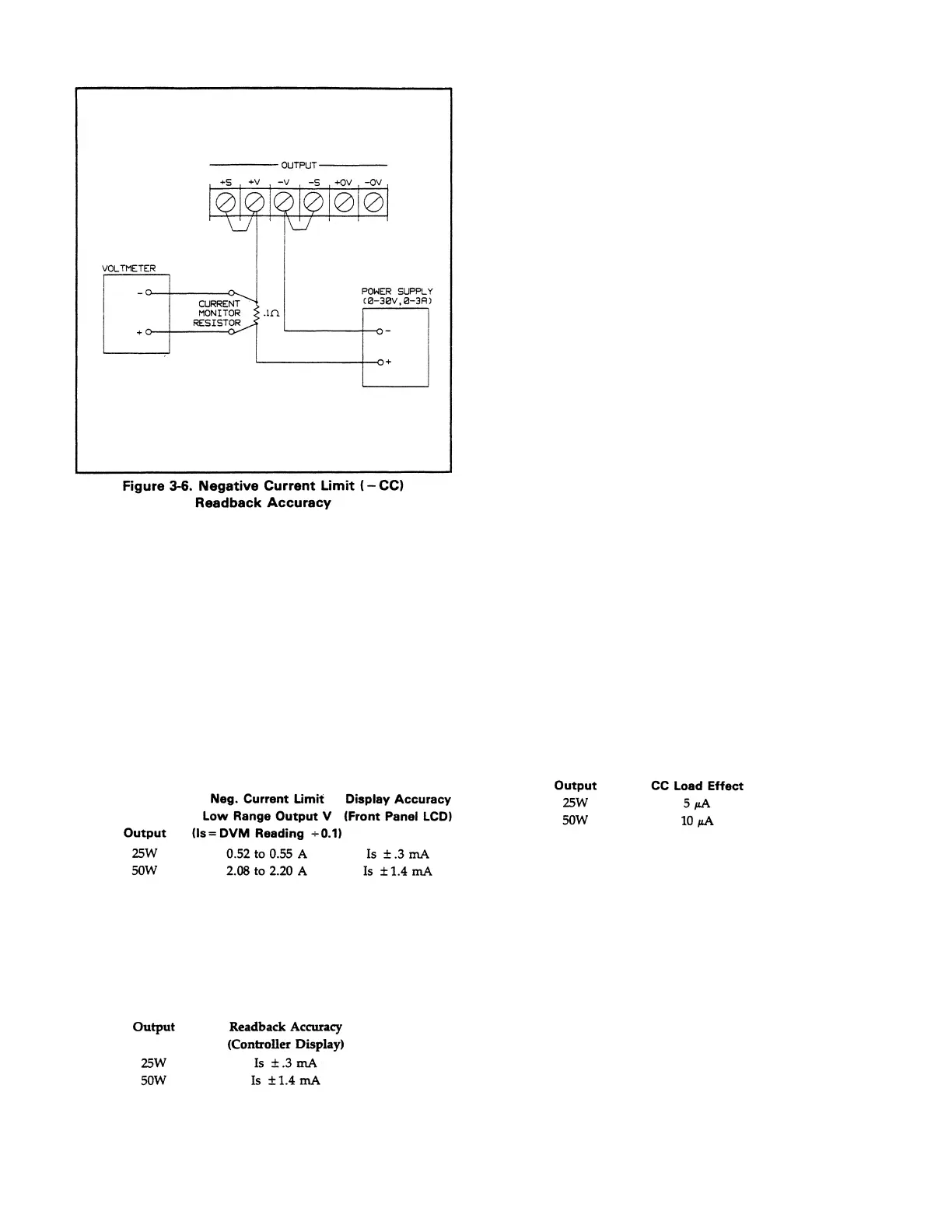
e. Divide the voltage drop across the current
monitoring resistor by the value 0.1 to obtain the
current sink value (Is) in amps and record the
value. Record also the current reading on the
display. The readings should be within the limits
specified below for the particular output type being
tested. Note that the CC annunciator must be on.
f. Read back the sink current from the selected
channel over the GPIB by entering and running
the program listed in paragraph 3-21.
g. Record the value displayed on the controller. This
value should be within the reading (Is) noted in
step e and the limits specified below.
h. For the 50 watt outputs only, raise the voltage of
the external supply up top approximately 30 V as
indicated on your supply’s front panel LCD and
Note that the sink current (Is) changes from the
previous value to between 1.04 and 1.10 amps.
i. Read back the sink current from the selected
channel over the GPIB by entering and running
the program listed in paragraph 3-21.
j. Read the value displayed on the controller. This
value should be Is (from step e) ± 0.9 mA.
k. Repeat this test (steps a through j for each output in
your supply
.
3-23 CC Load Effect. This test measures the change in
output current for a change in the load from 50 Volts to short
circuit.
a. Turn off the supply and connect the output to be
tested as shown in Figure 3-3 with the DVM
connected across the current monitoring resistor,
the load switch closed, and the short switch
opened.
b. Turn on the supply and select the output to be
tested (OUTPUT SELECT key on the front panel).
c. Program the current of the selected output to the
High Range Full Scale Current value and the
output voltage to 50.5 volts by sending the
following strings:
ISET <ch>, <0.5(25W) or 1(50W)>
VSET <ch>, <50.5>
d. Adjust the load for High Range Full Scale current
and 50 Volts as indicated on the front panel display.
Check that the CC annunciator is on. If it is not,
adjust the load so the output voltage drops slightly.
e. Record the output current reading (DVM reading
÷0.1).
f. Close the short switch and record the output
current reading. The difference in the current
readings in steps e and f is the load effect and
should not exceed the value listed below for the
particular output being tested.
g. Repeat this test (steps a through f) for each output
in your supply.
3-24 CC Source Effect. This test measures the change in
output current that results when the ac line voltage changes
from the minimum to the maximum value within the
specifications.
a. Turn off the supply and connect the ac power line
through a variable voltage transformer.
b. Connect the output to be tested as shown in Figure
3-3 with the DVM connected across the current
monitoring resistor, the load switch closed, and the
short switch opened.
c. Adjust the transformer to 13% below the nominal
line voltage.
d. Turn on the supply and select the output to be
tested (OUTPUT SELECT key on the front panel).
3-9
Artisan Scientific - Quality Instrumentation ... Guaranteed | (888) 88-SOURCE | www.artisan-scientific.com

 Loading...


