i. Repeat steps f and g. Note the difference between
the values read before and after the temperature
change. The difference between the output voltage
DVM readings should be less than 16 mV. The
difference between the readback voltage should be
less than the change in output ± 15 mV.
j. Repeat steps a through I for each output in your
supply.
3-35 Output Current and Readback Current TC
a. Repeat steps a through d of paragraph 3-34.
b. Set the temperature chamber to 30 degrees C and
allow 30 minutes for the output to stabilize.
c. Record the output current (DVM reading ÷ 0.1
(Shunt resistance)).
d. Readback the output current over the GPIB and
record the value.
e. Increase the temperature to 40 degrees C and wait
30 minutes for the output to stabilize.
f. Repeat steps c and d. Note the difference between
the values read before and after the temperature
change. The differences in output current should
not be more than 240
µ
A(25W) or 1.2 mA(50W).
The difference between the readback currents
should be less than the change in output ± 265
µ
A(25W) or 1.15 mA(50W).
g. Repeat steps a through f for each output in your
supply.
3-36 Negative Current Limit ( - CC) Readback TC
a. Repeat steps a through d of paragraph 3-22.
b. Set the temperature chamber to 30 degrees C and
allow 30 minutes for the output to stabilize.
c. Record the negative current limit value (DVM
reading x 10).
d. Readback the current over the GPIB and record
this value.
e. Increase the temperature to degrees C and wait 30
minutes for the output to stabilize.
f. Repeat steps c and d. Note the difference between
the values read before and after temperature
change. The differences should not be more than
the change I the sink current ± 265 µA(25W) or 1.15
mA(50W).
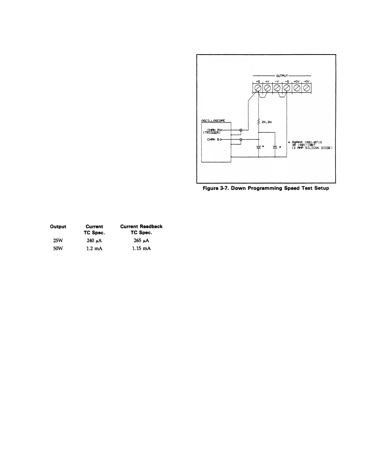
3-37 CV Down Programming Speed. This test measures
the time required for the output voltage to fall 37% of the
High Range Full Scale Voltage (time constant). Also
measured is the time an output takes to change from full
scale to zero volts and settle within 50 mV (response time).
a. Turn off the supply and connect the output to be
tested as shown in Figure 3-7.
b. Turn on the supply and select the output to be
tested (OUTPUT SELECT key on the front panel).
c. First, program the selected output to zero volts by
sending the string:
VSET <ch>, 0
d. Using Channel A on the oscilloscope, set the
volts/division switch to 10 V/div, dc coupled and
position the trace on the bottom horizontal line.
Using Channel B on the oscilloscope, set the
volts/division switch to 50 mV/div dc coupled and
position the trace on the bottom horizontal line.
e. Program the output voltage in a loop which
alternately programs the output voltage between 0
and 50 volts by running the program listed below.
10 OUTPUT 705;”ISET <ch>, <0.515(25W)
or 1.03(50W) >
20 OUTPUT 705;”VSET <ch>,0”
30 WAIT 0.05
40 OUTPUT 705;”VSET <ch>, 50”
50 WAIT 0.05
60 GOTO 20
70 END
NOTE
The tested output’s CV annnciator should remain on at all
times while the test is in progress.
f. Observe Channel A on the oscilloscope and adjust
for a stationary waveform by using Channel A as
the trigger source set to trigger on a negative edge.
Be sure to trigger as lose as possible to the time
when the output voltage just begins to fall.
3-12
Artisan Scientific - Quality Instrumentation ... Guaranteed | (888) 88-SOURCE | www.artisan-scientific.com

 Loading...


