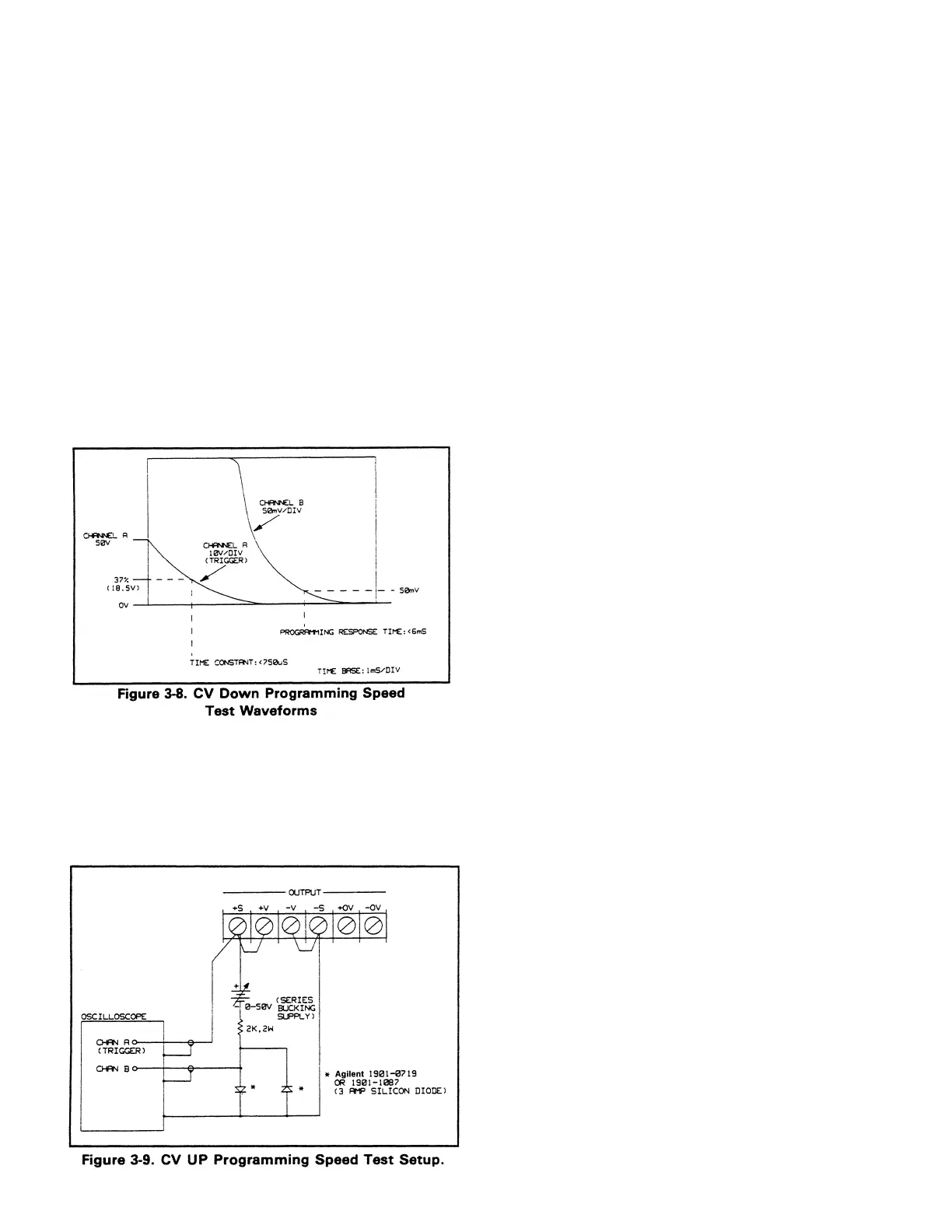
g. On Channel A, observe the output voltage
transition from the High Range Full Scale Voltage
to the scope's bottom horizontal line. Look for a
smooth exponential waveform with no "kinks" or
aberrations. Perform a time constant check by
insuring that the output voltage falls to about (37%)
18.5 V in less than 750 µS. Refer to the Channel A
waveform shown in Figure 3-8.
h. Now observe Channel B on the oscilloscope while
maintaining the trigger on Channel A as in step f.
Note that the diode clamp, used in the test setup of
Figure 3-7 prevents gross overload of Channel B
(which is set at 50 mV/div) allowing examination
of the "tail" of the exponential waveform. The
output voltage should be within 50 mV of its final
settling value on the bottom horizontal line in less
than 6 msec. Refer to the Channel B waveform
shown in Figure 3-8.
i. Repeat steps a through h for each output in your
supply.
3-38 CV UP Programming Speed.
This test measures the
time required for the output voltage to rise to 63% of the
high range full scale voltage (time constant). Also measured
is the time the output takes to change from .4 volts to full
scale and settle within 50 mV (response time).
a. Turn off the supply and connect the output to be
tested as shown in Figure 3-9.
b. Turn on the supply and select the output to be
tested (OUTPUT SELECT key on the front panel).
c. First, program the selected output’s voltage to 50
volts by sending the following string:
VSET < ch>, 50
d. Set the vertical sensitivity switch of Channel A on
the oscilloscope to 10 V/div. With the
oscilloscope’s input switch in GND position, adjust
the trace to the bottom horizontal line. Then set the
input switch to the dc coupled position. Set the
vertical sensitivity switch of channel B on the
oscilloscope to 50 mV/div and the input switch to
the GND position.
e. Adjust the Channel B trace to the top horizontal
line of the oscilloscope and move the input switch
to the DC position.
f. Adjust the bucking supply until the Channel B
trace is as close as possible (within 1 division) to
the top horizontal line and then use the scope
vertical adjust to fine adjust the trace to the top
horizontal line.
g. Program the output voltage in a loop which
alternately programs the output voltage between
0.4 V and 50 V by running the following program:
10 OUTPUT 705;”ISET <ch>, <0.515(25W)
or 1.03(50W) >
20 OUTPUT 705;”VSET <ch>,50”
30 WAIT 0.05
40 OUTPUT 705;”VSET <ch>, 4”
50 WAIT 0.05
60 GOTO 20
70 END
NOTE
The tested output’s CV annnciator should remain on at all times
while the test is in progress.
h. Observe Channel A on the oscilloscope and adjust
for a stationary waveform by using Channel A as
the trigger source set to trigger on a positive edge.
Be sure to trigger as close as possible to the time
when the output voltage just begins to rise.
i. On Channel A, observe the output voltage
transition from the scope’s bottom horizontal line
to 50 volts. Look for a smooth exponential
waveform with no by insuring that the output
voltage rises to about 31.5 volts (63%) in less than
750 µsec. Refer to the Channel A waveform shown
in Figure 3-10.
j. Now observe Channel B on the oscilloscope while
maintaining the trigger on Channel A as in step h.
Note the series supply bucks out the Full Scale
Output Voltage and that the waveform is clamped
at approzimately – 0.6 V and rises to the top
horizontal line when the output voltage is at full
3-13
Artisan Scientific - Quality Instrumentation ... Guaranteed | (888) 88-SOURCE | www.artisan-scientific.com

 Loading...


