c.
Remove the two screws on each side of front panel.
d.
Slide the panel forward.
4-11 Chassis Mounted Components
The power transformer is fastened to a mounting bracket by
mounting screws, flat washers, and shoulder washers.
Before removing the attaching hardware, disconnect the
power cable leads at the transformer.
When replacing the transformer, refer to the label on the
transformer to ensure you reconnect the leads correctly. You
can also refer to Figure 6-1 which shows all AC connections
schematically for each of the models.
The fan and fan guard are secured to the chassis by
mounting screws, flat washers, and nuts. Remove this
hardware, disconnect the ac connector on the fan assembly,
and lift the fan from the unit.
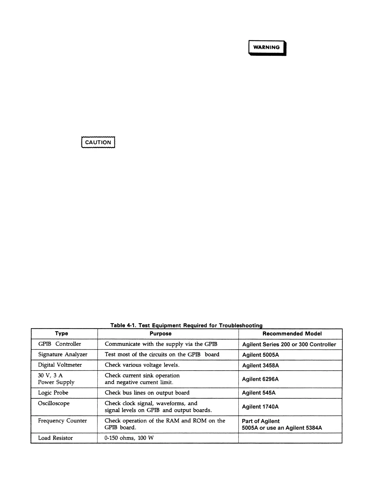
4-12 TEST EQUIPMENT REQUIRED
Table 4-1 lists the test equipment required to troubleshoot
the power supply. Recommended models are listed.
4-13 FUSE REPLACEMENT
Table 4-2 gives the rating of the fuses in the supplies. The
clip mounted ac line fuse is located in the line module on the
rear of the supply. The line module also contains a voltage
selection card which must be set to the associated ac input
(100, 120, 220, or 240 VAC). Section II in the Operating
Manual (Agilent 5957-6332) explains how to change the line
voltage setting.
The GPIB board has one fuse F201 as shown in Figure 4-2.
The output board fuse locations are shown in Figures 4-3
and 4-4. The fuses are shown schematically in Figures 6-1
through 6-3 in the rear of this manual.
4-5
b. Remove the rack ears or vinyl trim from the sides
of the front panel.
To avoid breaking the transformer tabs (lugs), do
not bend the transformer tabs. When
disconnecting a lead, pull the lead connector
straight back from the tab. When reconnecting a
lead, push the connector straight forward onto the
transformer tab. Do not flex the leads or tabs
when making connections or disconnections.
Be sure to remove the AC line cord from the unit
before attempting to work on the AC line module.
To remove the AC line module, first disconnect all of the
wires from it (including the RFI capacitor). Then use a
screwdriver inside the unit to press the mounting clip on one
side of the line module and push (from inside the unit) that
side of the module slightly away from the chassis. Finally,
use the screwdriver again to press on the mounting clip on
the other side of the module and push that side out. The
module can be replaced simply by sliding it straight back
into the mounting hole until the mounting clips spring into
position securing the module. The wires can be replaced
according to the .AC connections shown in Figure 6-1.
Artisan Scientific - Quality Instrumentation ... Guaranteed | (888) 88-SOURCE | www.artisan-scientific.com

 Loading...


