200 MHz
Loop Gain
Adjustment
11.
In
the A6
adjustment
menu,
select the
A6
lo
op
gain
adjustmen
t,
N
NN
NN
NN
NN
NN
NN
NN
N
N
N
N
N
N
N
N
N
N
N
NN
NN
NN
NN
NN
NN
A6
Loop Gain
.The
synthesizer
automatically p
erforms the
adjustment.
When the
message
Calibration
Constants
should be
SAVED
is
displa
y
ed,
the
adjustmen
t
is
complete.
Con
tinue
with the
next
step.
12. Set
the syn
thesizer to
standby
.
Reinstall
the
A6
assem
bly
in
the
instrumen
t,
and
connect
all
cables.
IF Gain
Adjustment
13.
T
urn
the
syn
thesizer
on.
Select
N
NN
NN
NN
N
N
N
N
N
N
N
N
N
N
N
N
N
N
N
N
N
NN
NN
NN
NN
A6
IF
Gain
.
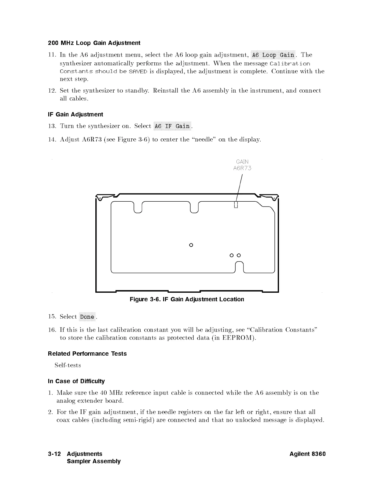
14.
Adjust
A6R73
(see
Figure
3-6)
to cen
ter the
\needle"
on
the
displa
y
.
Figure
3-6.
IF
Gain
Adjustment Location
15.
Select
N
N
N
N
N
N
N
N
N
N
N
N
N
N
Done
.
16.
If
this
is
the
last
calibration
constan
t
y
ou
will b
e
adjusting,
see
\Calibration
Constan
ts"
to store the calibration constan
ts as protected data (in EEPR
OM).
Related P
erformance T
ests
Self-tests
In Case of Difficulty
1. Make sure the 40 MHz reference input cable is connected while the A6 assembly is on the
analog extender b oard.
2. For the IF gain adjustment, if the needle registers on the far left or right, ensure that all
coax cables (including semi-rigid) are connected and that no unlo cked message is displayed.
3-12 Adjustments
Sampler Assembly
Agilent 8360
 Loading...


