EasyManuals Logo

Agilent Technologies 8360 B Series Service Guide

Agilent Technologies 8360 B Series
603 pages
To Next Page IconTo Next Page
To Previous Page IconTo Previous Page
Page #473 background imageLoading...
Page #473 background image
3.
A20 RF
Interface Remo
v
al
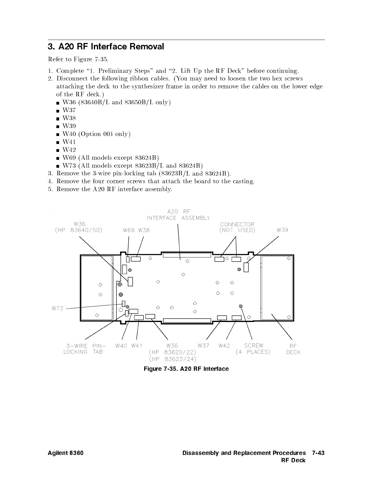
Refer to
Figure 7-35
.
1.
Complete
\1.
Preliminary
Steps"
and
\2. Lift
Up the
RF Dec
k" b
efore con
tinuing.
2.
Disconnect the
following
ribb on
cables. (Y
ou ma
y
need
to
lo
osen
the
t
w
o
hex
screws
attac
hing
the
dec
k
to
the
syn
thesizer
frame
in
order
to
remo
v
e
the
cables on
the lo
wer
edge
of
the
RF
dec
k.)
W36
(83640B
/L and
83650B/L
only)
W37
W38
W39
W40
(Option
001
only)
W41
W42
W69
(All
mo
dels
except
83624B
)
W73
(All
mo
dels
except
83623B
/L and
83624B)
3.
Remo
ve
the
3-wire
pin-lo
c
king
tab
(
83623B
/L
and
83624B
).
4.
Remo
v
e
the
four
corner
screws that
attach
the b
oard
to
the
casting.
5.
Remo
v
e
the
A20
RF
in
terface
assem
bly
.
Figure 7-35. A20 RF Interface
Agilent 8360 Disassembly and Replacement Procedures
RF Deck
7-43

Table of Contents

Other manuals for Agilent Technologies 8360 B Series

Questions and Answers:

Question and Answer IconNeed help?

Do you have a question about the Agilent Technologies 8360 B Series and is the answer not in the manual?

Agilent Technologies 8360 B Series Specifications

General IconGeneral
BrandAgilent Technologies
Model8360 B Series
CategoryPortable Generator
LanguageEnglish

Related product manuals