EasyManuals Logo

Agilent Technologies 8360 B Series Service Guide

Agilent Technologies 8360 B Series
603 pages
To Next Page IconTo Next Page
To Previous Page IconTo Previous Page
Page #499 background imageLoading...
Page #499 background image
4.
J1 RF
Output Connector
Remo
v
al
(Option
004)
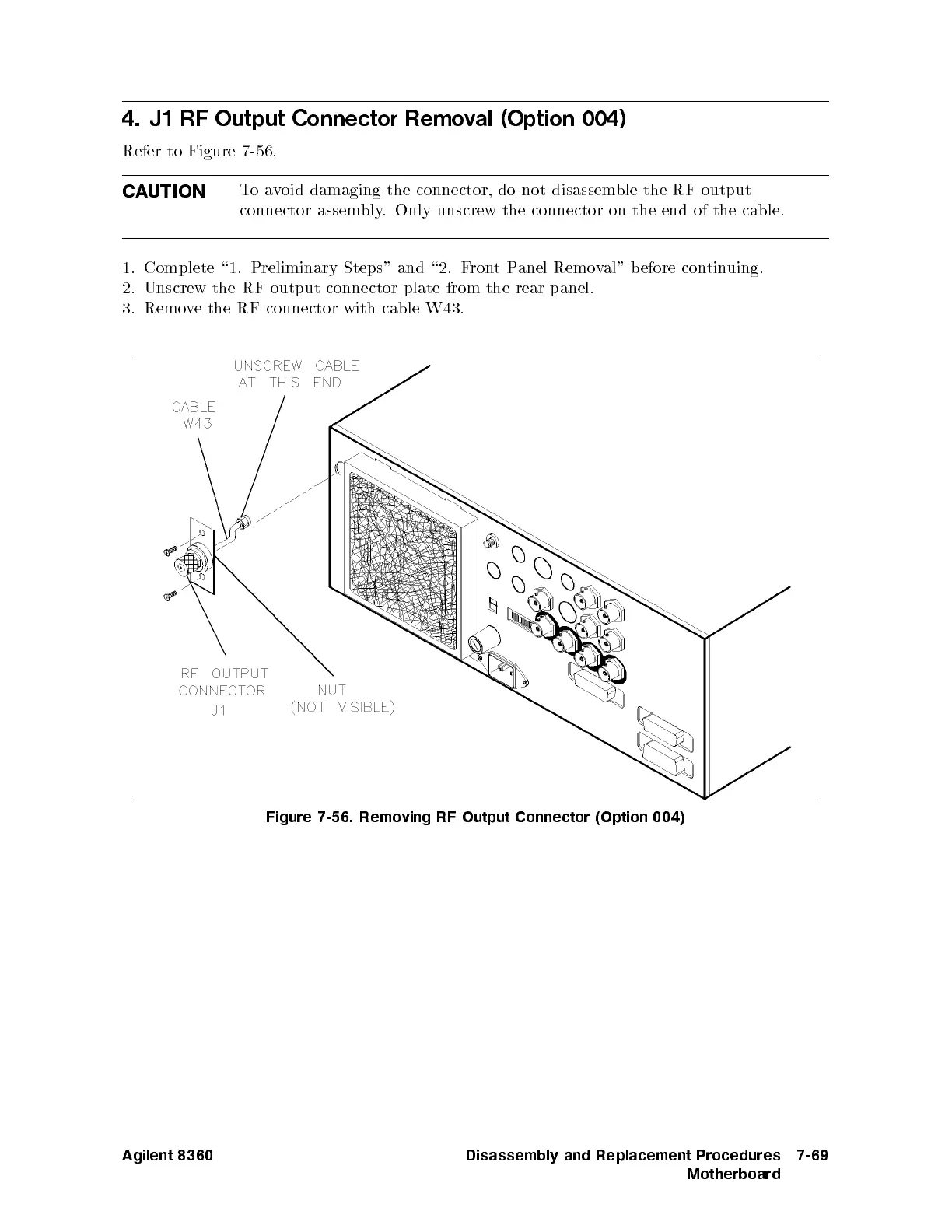
Refer to
Figure 7-56
.
CA
UTION
T
o
a
v
oid
damaging
the
connector,
do
not
disassemble
the RF
output
connector
assembly
. Only
unscrew the
connector on
the end
of the
cable.
1. Complete
\1. Preliminary
Steps" and
\2. F
ron
t
P
anel
Remo
v
al"
b
efore
con
tin
uing.
2.
Unscrew
the
RF
output
connector
plate
from
the
rear
panel.
3.
Remo
v
e
the
RF
connector
with cable
W43.
Figure
7-56.
Remo
ving
RF
Output
Connector
(Option
004)
Agilent 8360 Disassembly and Replacement Procedures
Motherboard
7-69

Table of Contents

Other manuals for Agilent Technologies 8360 B Series

Questions and Answers:

Question and Answer IconNeed help?

Do you have a question about the Agilent Technologies 8360 B Series and is the answer not in the manual?

Agilent Technologies 8360 B Series Specifications

General IconGeneral
BrandAgilent Technologies
Model8360 B Series
CategoryPortable Generator
LanguageEnglish

Related product manuals