Procedure
1.
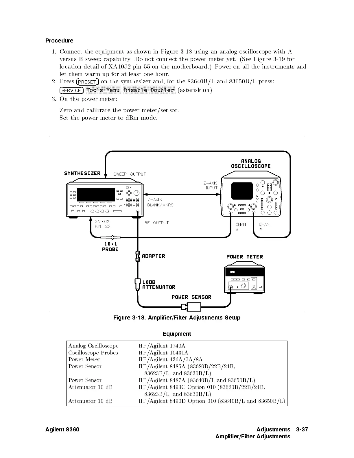
Connect
the
equipmen
t
as
sho
wn
in Figure
3-18 using
an analog
oscilloscop e
with A
v
ersus B
sweep
capability
.Do
not connect
the p
o
w
er
meter
y
et.
(See
Figure
3-19
for
lo cation
detail of
XA10J2
pin
55
on
the
motherb
oard.)
P
o
w
er
on all
the instrumen
ts and
let
them
w
arm
up
for
at least
one hour.
2.
Press
4
PRESET
5
on the
synthesizer
and, for
the 83640B
/L
and
83650B
/L
press:
4
SERVICE
5
N
NN
NN
NN
NN
N
N
N
N
N
N
N
N
N
N
N
N
N
N
N
N
N
NN
NN
NN
Tools
Menu
N
NN
NN
NN
NN
N
N
N
N
N
N
N
N
N
N
N
N
N
N
N
N
N
NN
NN
NN
NN
N
N
N
N
N
N
N
N
N
N
N
N
N
Disable
Doubler
(asterisk
on)
3.
On
the
p
o
wer
meter:
Zero
and
calibrate
the
po
wer
meter/sensor.
Set
the p
o
w
er
meter
to
dBm
mo
de.
Figure 3-18. Amplifier/Filter Adjustments Setup
Equipment
Analog Oscilloscop e
HP/Agilent 1740A
Oscilloscope Prob es
HP/Agilent
10431A
Power Meter
HP/Agilent 436A/7A/8A
Power Sensor
HP/Agilent 8485A (83620B/22B/24B,
83623B/L, and 83630B/L)
Power Sensor HP/Agilent 8487A (83640B/L and 83650B /L)
Attenuator 10 dB HP/Agilent 8493C Option 010 (83620B/22B/24B,
83623B/L, and 83630B/L)
Attenuator 10 dB HP/Agilent 8490D Option 010 (83640B/L and 83650B/L)
Agilent 8360 Adjustments
Amplifier/Filter Adjustments
3-37
 Loading...


