EasyManuals Logo

Agilent Technologies 8360 B Series Service Guide

Agilent Technologies 8360 B Series
603 pages
To Next Page IconTo Next Page
To Previous Page IconTo Previous Page
Page #444 background imageLoading...
Page #444 background image
8.
Front P
anel BNC
Connectors
Remo
v
al
Refer to
Figure 7-11
.
1.
Complete
\1.
Preliminary
Steps",
\2.
Fron
tP
anel Remo
val",
\3. A3
Fron
tP
anel
Pro
cessor
Remo
val"
and \5.
A2 Source
Mo dule
Interface
Remo
v
al"
b
efore
con
tin
uing.
2.
Remo
v
e
the
t
w
o
screws
on
eac
h
of
the
four
PC
assem
blies attac
hed to
the bac
kof
the
fron
t
panel.
3.
Slide out
the connectors.
Note
If
the
w
asher
on
the
fron
t
of the
connector is
not cen
tered prop
erly
,
lo
osen
the
n
ut to
slide the
connector out.
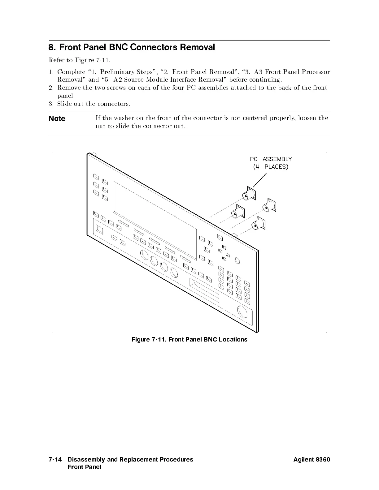
Figure 7-11. Front P
anel BNC Locations
7-14 Disassembly and Replacement Procedures
Front Panel
Agilent 8360

Table of Contents

Other manuals for Agilent Technologies 8360 B Series

Questions and Answers:

Question and Answer IconNeed help?

Do you have a question about the Agilent Technologies 8360 B Series and is the answer not in the manual?

Agilent Technologies 8360 B Series Specifications

General IconGeneral
BrandAgilent Technologies
Model8360 B Series
CategoryPortable Generator
LanguageEnglish

Related product manuals