6.
Maximum Lev
eled P
o
w
er
Note
This
performance
test is
not v
alid unless
the syn
thesizer
meets
b
oth
its
p
o
w
er
accuracy and
p
o
w
er
atness
sp
ecications.
P
erform
those
tests
rst.
Description
and
Procedure
The
unlev
eled
status
indicator
is
displa
y
ed
when
the
instrumen
t
is
unlev
eled as
the syn
thesizer
sw
eeps
o
v
er
sp
ecic frequency
ranges in
fast con
tinuous
sw
eep,
and
fast
and
slo
w
single
sw
eep
op
eration. Because
of the
syn
thesizer's
p
o
w
er
accuracy
and
atness
p
erformance,
a
p
o
w
er
meter
is
not
required
for
this
measuremen
t.
The
follo
wing
pro
cedure
tests
the
most lik
ely
w
orst
case
situations
for
maxim
um lev
eled p
ow
er.
1.
Set up
and
turn
on
the
equipmen
t
sho
wn
in
Figure
2-7
.
Preset
the
syn
thesizer
and
let
it
w
arm
up
for
at
least
one
hour.
Note
The
20
dB
atten
uator
pro
vides
a
go
o
d
matc
h
on
the
RF
output. If
the
syn
thesizer
has
a
step
atten
uator,
y
ou
can
sim
ulate
a
go
o
d
match
by
decoupling the
step atten
uator from
the
ALC
and
setting
the
atten
uator
to
20
dB.
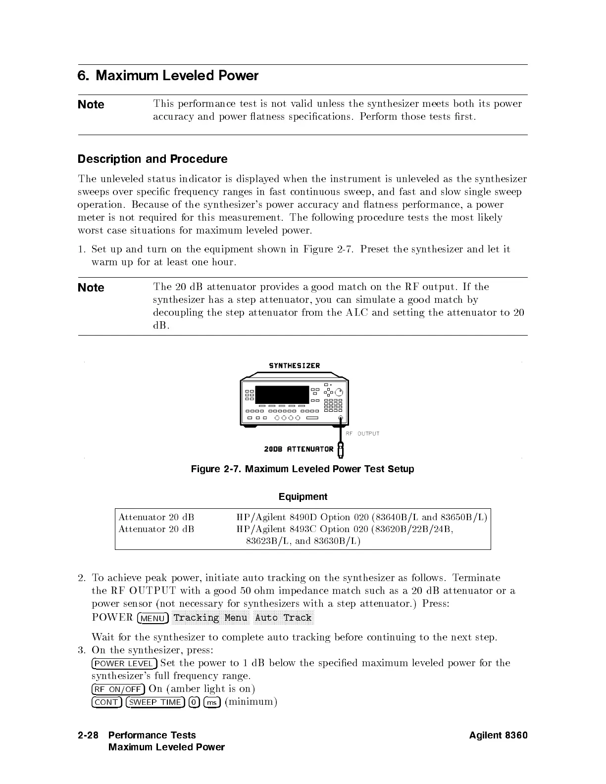
Figure
2-7. Maximum
Leveled
Po
w
er
T
est
Setup
Equipment
Atten
uator
20
dB
HP/Agilen
t
8490D
Option
020
(
83640B
/L
and
83650B
/L)
A
tten
uator
20
dB
HP/Agilen
t 8493C
Option
020
(
83620B
/22B/24B,
83623B/L, and 83630B /L)
2. T
oac
hieve peak p o
wer, initiate auto trac
king on the syn
thesizer as follo
ws. T
erminate
the RF OUTPUT with a go o d 50 ohm imp edance matc
hsuc
has
a 20 dB atten
uator or a
po
wer sensor (not
necessary for syn
thesizers with a step atten
uator.) Press:
PO
WER
4
MENU
5
NNNNNNNNNNNNNNNNNNNNNNNNN
NNNNNNNNNNNNNNNN
Tracking
Menu
NNNNNNNNNNNNNNNNNNNNNNNNN
NNNNNNN
Auto
Track
Wait for the synthesizer to complete auto tracking b efore continuing to the next step.
3. On the synthesizer, press:
4
POWER LEVEL
5
Set the p ower to 1 dB b elow the sp ecied maximum leveled p ower for the
synthesizer's full frequency range.
4
RF ON/OFF
5
On (amber light is on)
4
CONT
54
SWEEP TIME
54
0
54
ms
5
(minimum)
2-28 Performance Tests
Maximum Leveled Power
Agilent 8360
 Loading...


