Procedure
Note
In
this
pro
cedure,
some
calibration
constan
ts
and
poten
tiometers ma
yb
e
set to
default conditions
and left.
This is
normal. These
boards
contain
adjustmen
ts for
dierent
vin
tages
of
the
8360
family
.
Not
all
adjustmen
ts
are
used
eac
h
time.
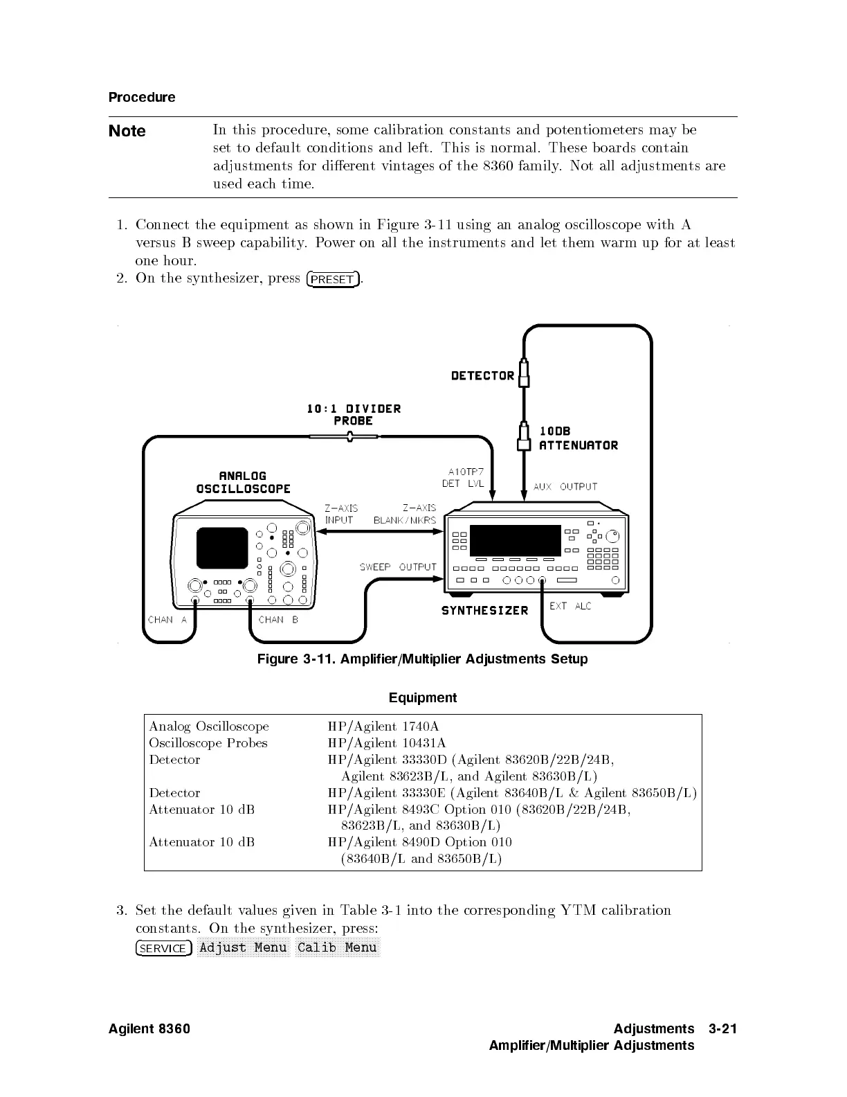
1.
Connect
the
equipment
as sho
wn in
Figure 3-11
using
an
analog
oscilloscop
e
with
A
versus
B
sw
eep
capabilit
y
.
P
o
w
er
on
all
the
instrumen
ts
and
let
them w
arm up
for at
least
one
hour.
2.
On the
synthesizer,
press
4
PRESET
5
.
Figure
3-11.
Amplifier/Multiplier
Adjustments
Setup
Equipment
Analog
Oscilloscop
e
HP/Agilen
t 1740A
Oscilloscop
e
Prob
es
HP/Agilen
t
10431A
Detector HP/Agilent 33330D (Agilen
t 83620B /22B/24B,
Agilent 83623B/L, and Agilen
t 83630B/L)
Detector HP/Agilent 33330E (Agilen
t 83640B/L & Agilen
t 83650B/L)
Attenuator 10 dB
HP/Agilent 8493C Option 010 (83620B /22B/24B,
83623B/L,
and 83630B/L)
Attenuator
10 dB
HP/Agilent 8490D Option 010
(83640B/L and
83650B/L)
3. Set the default values given in Table 3-1 into the corresp onding YTM calibration
constants. On the synthesizer, press:
4
SERVICE
5
NNNNNNNNNNNNNNNNNNNNNNNNNNNNNNNNNNN
Adjust Menu
NNNNNNNNNNNNNNNNNNNNNNNNNNNNNNNN
Calib Menu
Agilent 8360 Adjustments
Amplifier/Multiplier Adjustments
3-21
 Loading...


