11.
ALC
Po
w
er
Lev
el
Accuracy
Description
and Procedure
This adjustmen
tsets
the absolute
po
wer
accuracy
in
eac
h
frequency
band
at
a
CW
frequency
.
The
digital
ALC
calibration
arra
y
is
loaded
with
zeros
for
the
0
dB
atten
uator
setting to
eliminate
an
y
po
wer
oset from
this source.
Calibration
constan
ts
set
the
p
o
w
er
accuracy
at
four p
o
w
er
lev
els.
A
p
oten
tiometer
sets
the
p
o
w
er
accuracy at
an 18
dBm lev
el in
the
lo
w
band
(not
applicable for
all mo
dels).
Note
This
adjustmen
t
pro
cedure
zeros
the
digital
ALC
calibration
array
at the
0dB
atten
uator setting.
The \P
ow
er
Flatness"
adjustmen
t
m
ust
b
e
p
erformed
after
this
pro
cedure.
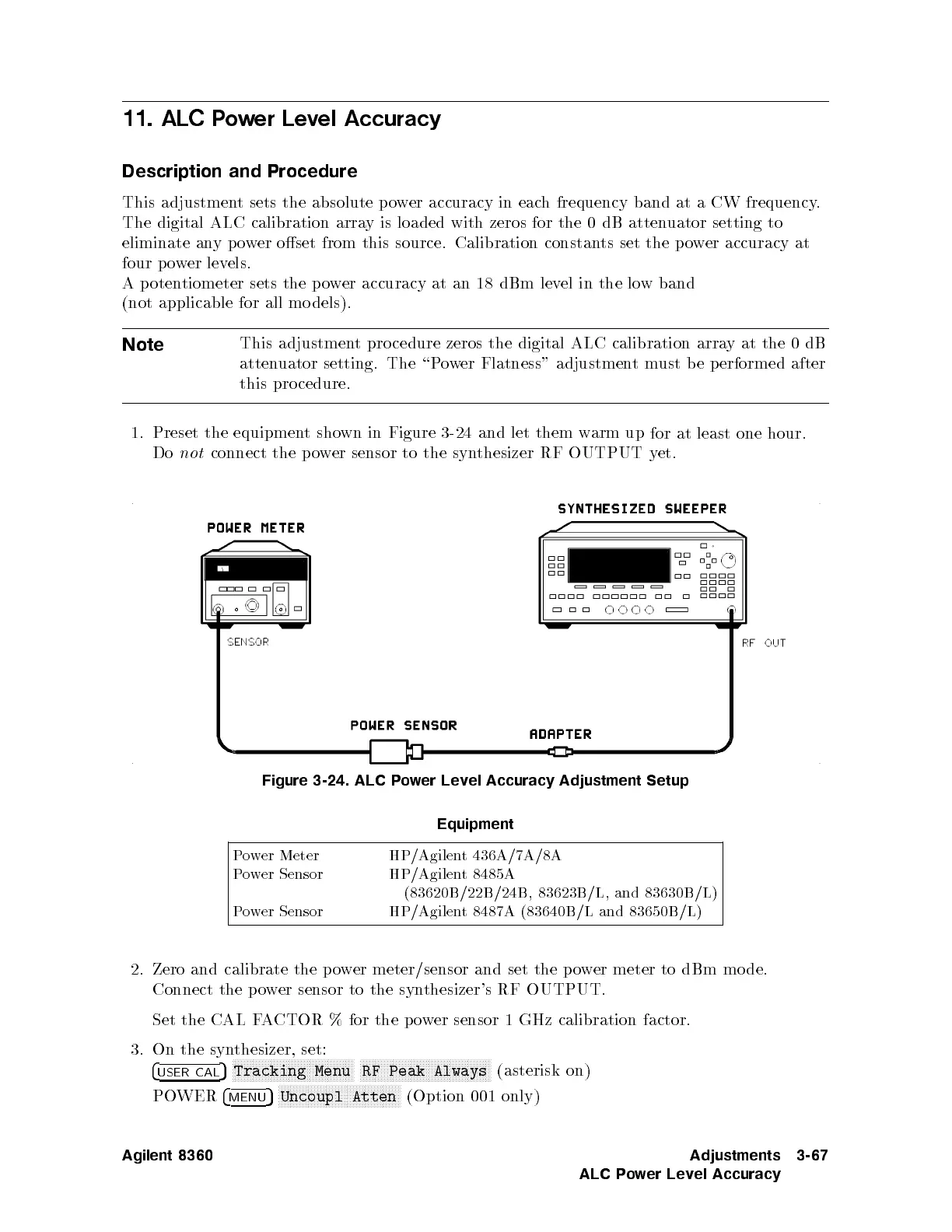
1.
Preset
the equipmen
t
sho
wn
in
Figure
3-24
and
let
them
w
arm
up
for
at
least
one
hour.
Do
not
connect
the
p
o
w
er
sensor
to
the
syn
thesizer
RF
OUTPUT
y
et.
Figure
3-24.
AL
C
Po
wer
Level
Accuracy Adjustment
Setup
Equipment
Power Meter
HP/Agilent 436A/7A/8A
Power Sensor
HP/Agilent 8485A
(83620B/22B/24B, 83623B/L, and 83630B/L)
Power Sensor
HP/Agilent 8487A (83640B/L and 83650B/L)
2. Zero and calibrate the po
wer meter/sensor and set the po
wer meter to
dBm mo de.
Connect the po
wer sensor to the
synthesizer's RF OUTPUT.
Set the CAL FACTOR % for the power sensor 1 GHz calibration factor.
3. On the synthesizer, set:
4
USER CAL
5
NNNNNNNNNNNNNNNNNNNNNNNNNNNNNNNNNNNNNNNNN
Tracking Menu
NNNNNNNNNNNNNNNNNNNNNNNNNNNNNNNNNNNNNNNNNNNN
RF Peak Always
(asterisk on)
POWER
4
MENU
5
NNNNNNNNNNNNNNNNNNNNNNNNNNNNNNNNNNNNNNNNN
Uncoupl Atten
(Option 001 only)
Agilent 8360 Adjustments
ALC Power Level Accuracy
3-67
 Loading...


