9.
On
the
syn
thesizer,
select
NN
NN
N
N
N
N
N
N
N
N
N
N
N
N
N
NN
NN
NN
NN
NN
NN
N
N
N
Modify
Cal
and,
using
the
rotary
knob,
mo
dify
the
calibration
constan
t
so
that
the
p
o
w
er
meter
and the
po
wer
level
setting are
the same.
10.
Repeat
steps 8
through 10
for eac
hp
ow
er lev
el
and
calibration
constan
t
giv
en
in
Table
3-9.
T
able
3-9.
Po
wer
Level
and Calibration
Constant
Adjustment
P
o
w
er
Level
(dBm)
Calibration
Constan
t
Adjustmen
t
0.0 #265
L
VL
D
A
C
Ofs
Lo Bnd
0
10.0
#252
L
VL
D
AC
Gain Lo
Bnd
0
20.0
#284
ALC
Det
Ofs;
Lo
+10.0 #293
ALC
Det
Log
Brkpt;
Lo
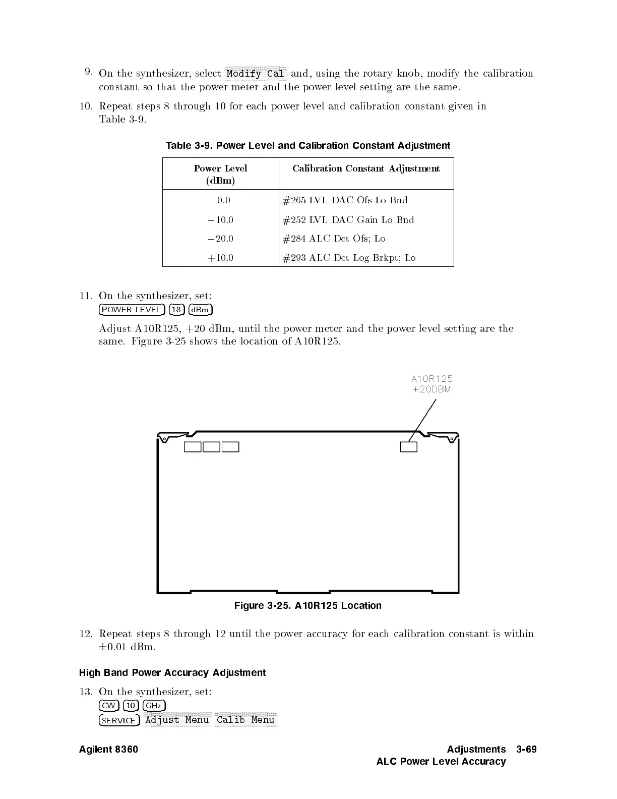
11.
On
the
syn
thesizer,
set:
4
PO
WER
LEVEL
5
4
18
5
4
dBm
5
Adjust
A10R125, +20
dBm, un
til the
po
w
er
meter
and
the
p
o
w
er
lev
el
setting
are
the
same.
Figure
3-25
sho
ws
the
lo
cation
of
A10R125.
Figure 3-25. A10R125 Location
12. Repeat steps 8 through 12 un
til the po
wer
accuracy for eac
h calibration constan
t is within
6
0.01 dBm.
High Band Power Accuracy Adjustment
13. On the synthesizer, set:
4
CW
54
10
54
GHz
5
4
SERVICE
5
NNNNNNNNNNNNNNNNNNNNNNNNNNNNNNNNNNN
Adjust Menu
NNNNNNNNNNNNNNNNNNNNNNNNNNNNNNNN
Calib Menu
Agilent 8360 Adjustments
ALC Power Level Accuracy
3-69
 Loading...


