12.
Po
wer
Flatness
(The
automated
po
wer
atness adjustmen
tin
Chapter 5
may
be
used
in
place
of
this
pro
cedure.)
Description and
Procedure
In
this pro
cedure,
the
syn
thesizer
measures
and
corrects
p
o
w
er
atness.
The
syn
thesizer
con
trols
the
p
o
w
er
meter
via
GPIB
while
the p
ow
er meter
is measuring
the
RF
output.
F
or
each
synthesizer
frequency band
and a
0
dB
atten
uator
setting,
con
trol
is
giv
en
to
the
syn
thesizer
to
measure
and
correct
p
o
w
er
atness.
Note
This
adjustmen
t
requires
an
HP/Agilen
t
437B
P
o
w
er
Meter.
The
correct
p
o
w
er
sensor
calibration
factors m
ust b
e loaded
and
selected.
This
pro
cedure
cannot
be
run
with
a
con
troller
on
the
GPIB,
nor
can
it
b
e
run
from
a
fron
t
panel
em
ulator.
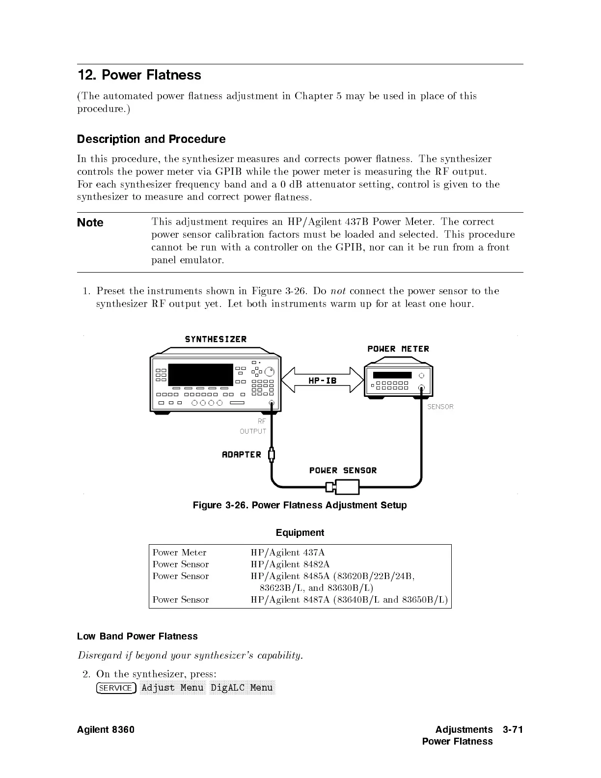
1.
Preset
the
instrumen
ts
sho
wn
in
Figure
3-26
.
Do
not
connect
the
p
o
w
er
sensor
to
the
syn
thesizer
RF
output
y
et.
Let
both
instruments
warm
up
for
at
least
one
hour.
Figure
3-26. P
o
w
er
Flatness
Adjustment
Setup
Equipment
P
ower Meter HP/Agilent 437A
Po
wer Sensor
HP/Agilent 8482A
Pow
er Sensor
HP/Agilent 8485A (83620B/22B/24B,
83623B/L, and 83630B /L)
Power Sensor
HP/Agilent 8487A (83640B/L and 83650B
/L)
Low Band Power Flatness
Disregardifbeyond your synthesizer's capability.
2. On the synthesizer, press:
4
SERVICE
5
NNNNNNNNNNNNNNNNNNNNNNNNNNNNNNNNNNN
Adjust Menu
NNNNNNNNNNNNNNNNNNNNNNNNNNNNNNNNNNN
DigALC Menu
Agilent 8360 Adjustments
Power Flatness
3-71
 Loading...


