EasyManuals Logo
Home>Agilent Technologies>Portable Generator>83650B

Agilent Technologies 83650B Service Guide

Agilent Technologies 83650B
603 pages
To Next Page IconTo Next Page
To Previous Page IconTo Previous Page
Page #494 background imageLoading...
Page #494 background image
1.
Preliminary Steps
CAUTION
Y
ou can
easily blo
w the
fuse for
the 13.5
V
supply
on
the
preregulator
assembly
if
y
ou
do
not
disconnect
the
A
C
p
o
wer
cord. Also,
the danger
of
sho
c
k
is
increased if
the p
ow
er cord
is connected.
1.
Disconnect
the
A
C
p
o
w
er
line
cord.
2.
Remo
ve
the screw
from eac
hof
the
four
feet
on
the
rear
panel.
3.
Remo
v
e
the
four
rear
feet.
4.
Remo
v
e
the
four
b
ottom
feet.
5. T
o remo
ve
the side
straps,
remo
v
e
the
t
w
o
screws
on
eac
h
side
panel.
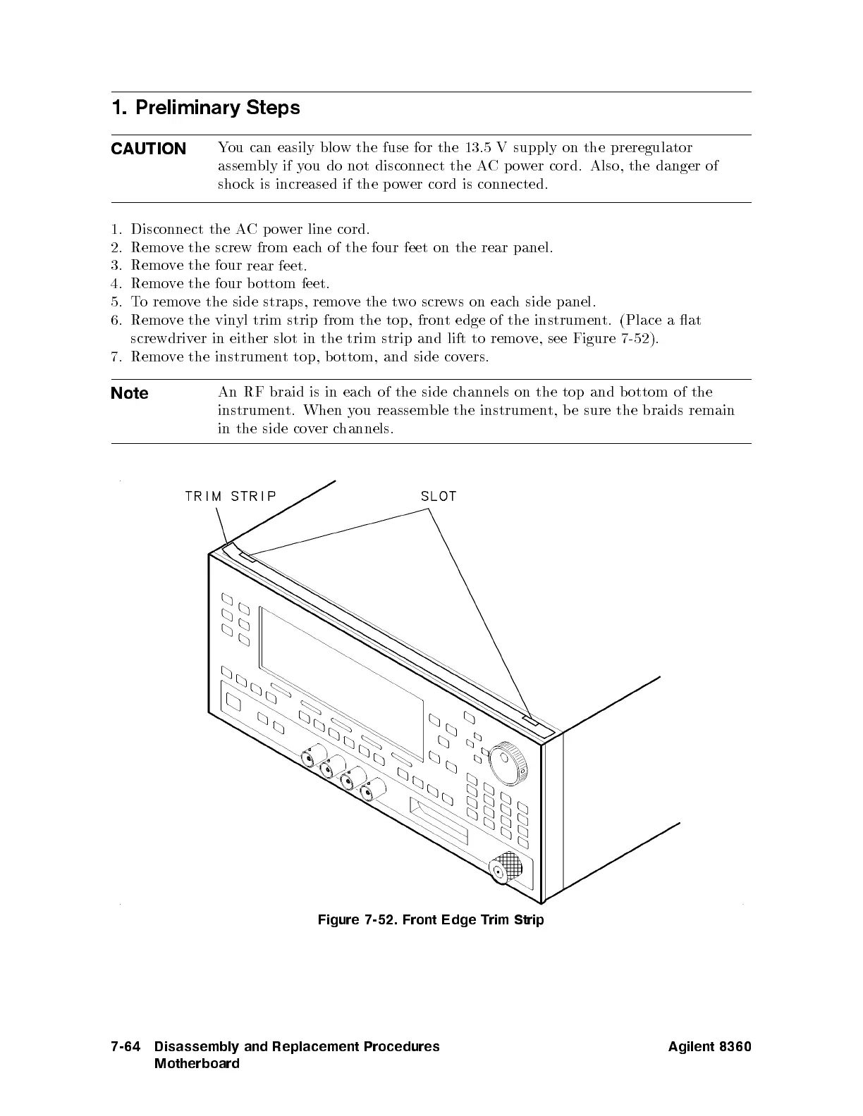
6.
Remo
v
e
the
vin
yl
trim
strip
from
the
top,
fron
t
edge
of
the
instrumen
t. (Place
a at
screwdriv
er
in
either
slot
in
the
trim
strip
and lift
to remo
ve,
see
Figure
7-52
).
7. Remo
ve
the instrumen
t
top,
b
ottom,
and
side
co
v
ers.
Note
An
RF
braid is
in
eac
h
of
the
side
c
hannels
on
the
top
and
b
ottom
of
the
instrumen
t.
When
y
ou
reassem
ble
the
instrumen
t,
b
e
sure
the
braids
remain
in
the side
co
v
er
c
hannels.
Figure 7-52. Front Edge Trim Strip
7-64 Disassembly and Replacement Procedures
Motherboard
Agilent 8360

Table of Contents

Other manuals for Agilent Technologies 83650B

Questions and Answers:

Question and Answer IconNeed help?

Do you have a question about the Agilent Technologies 83650B and is the answer not in the manual?

Agilent Technologies 83650B Specifications

General IconGeneral
BrandAgilent Technologies
Model83650B
CategoryPortable Generator
LanguageEnglish

Related product manuals