Installation Guide 7
E440xBU Option H70 Installation
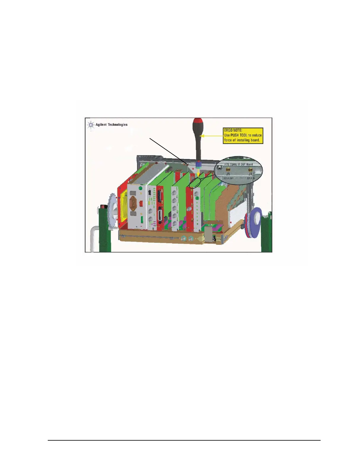
3. Insert the new 70MHz IF Board (E4404-60034) into option slot 5. Press the board firmly
into the place and secure with screw (0515-0372).
4. Connect cable “40” (E4440-60411) to the 70 MHz IF board (J1) and cable “51”
(E4440-60422) to the 70 MHz IF board (J5).
Figure 4 70 MHz IF Output Board
5. Reinstall the front frame assembly, vibration support, chassis cover, and instrument
cover in reverse order of the removal process described in the ESA Service Guide.
This concludes the installation of the E440xBU Option H70 into the ESA instrument.
 Loading...


