10 Installation Note E4440-90611
Installation Procedure
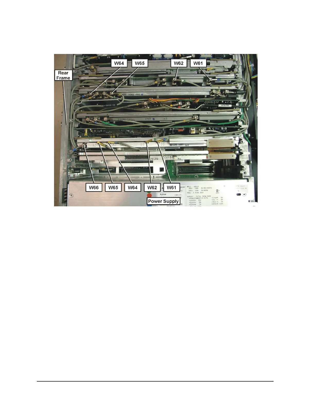
Figure 5 Cable Routing
11.Reinstall the A10 3rd Converter assembly. Re-attach all cables being sure to follow
the color code on the board.
12.Locate the cable with the “60” color code in the kit. Connect the SMB end to the A10
3rd Converter J6 (60). Route the cable along the rear frame and tuck the cable under
the top brace mounting tab so the cable will lay tightly against the rear frame.
Continue routing the cable between the A31 Wideband Analog IF and A32 Wideband
Digital IF assemblies. This routing is critical. Connect the other end to the A31
Wideband Analog IF at the jack marked “60”.
13.Locate the cable with the “40” color code in the kit. Connect the SMB end to the A10
3rd Converter J4 (40). Route the cable along the rear frame. Continue routing the
cable between the A31 Wideband Analog IF and A32 Wideband Digital IF assemblies.
This routing is critical. Connect the other end of the cable to the A31 Wideband
Analog IF at the jack marked “40”.

 Loading...


