Installation Note E4440-90611 9
Installation Procedure
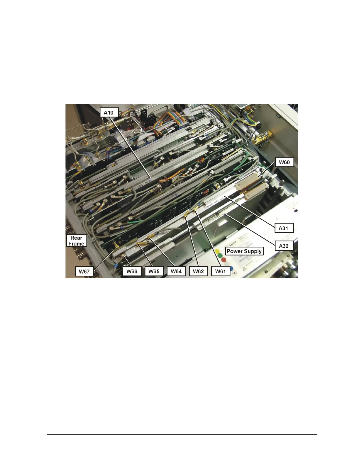
5. Refer to Figure 4. Install the A31 Wideband Analog IF assembly into the board slot
next to the A7 Digital IF. This slot is the third slot from the power supply.
6. Locate in the kit, and install the A32 Wideband Digital IF assembly next to the A31
Wideband IF assembly just installed.
Figure 4 Option 122 Assembly and Cable Locations
7. Remove all cables from the A10 3rd Converter assembly. Please note that all cables
are color-coded and the cable color is silk-screened on the 3rd Converter board.
Remove the 3rd Converter from the instrument.
8. Remove the 321.4 MHz IF Out SMA cable from the rear panel. Use the 8mm deep
socket or open end wrench. Avoid scratching the dress panel.
9. Locate in the kit, and install the replacement 321.4 MHz IF Out cable W66, that has
the 66 color bands. Install the washer between the nut and the rear panel and Torque
to 21 inch pounds.
10.Refer to Figure 5. Route the end of the W66, 321.4 MHz Out cable along the rear
frame and leave the SMB end near, but not attached to the SMB connector on the A31
Wideband Analog IF. Tuck the cable under the top brace mounting tab so the cable
will lay tightly against the rear frame.

 Loading...


