12 Installation Note E4440-90611
Installation Procedure
Changes to the RF Section
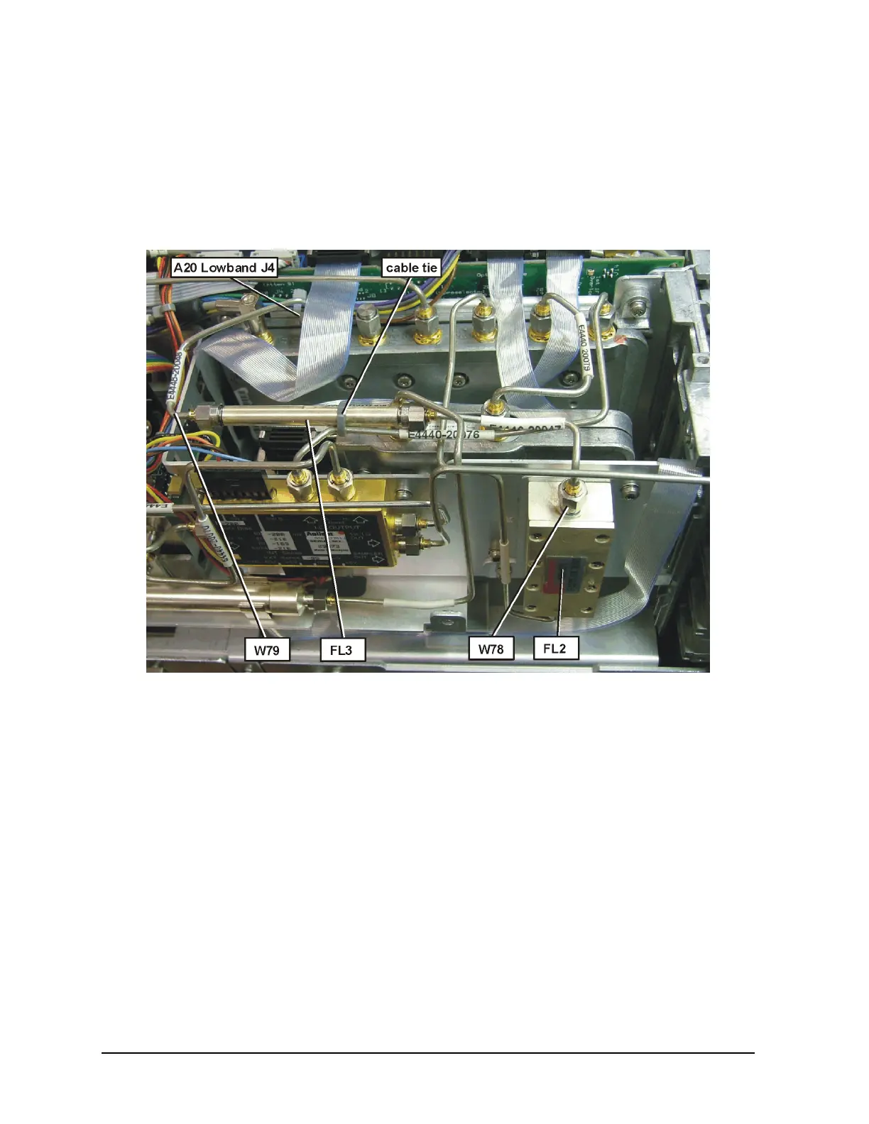
18.Figure 6 shows the completed installation of replacement filter FL2, the additional
filter FL3 and the associated cables. Refer to this figure when completing the rest of
the installation, and to determine the location of the components.
Figure 6 RF Section Part Locations
19.Locate FL2 in the instrument and completely remove the cable that connects from the
top of the filter to the A20 Lowband Assembly at J4. Discard this cable.
20.Disconnect the cable from the bottom of FL2. Do not remove the other end of this
cable.
21.Remove the two screws that secure the FL2 bracket, and remove the filter/bracket
assembly.
22.Remove the 3 screws that secure the filter to the bracket and discard the filter.
23.Locate the FL2 replacement filter in the kit and install it on the bracket and then
install the filter /bracket assembly. Torque screws to 9 inch pounds.
24.Reinstall the cable to the bottom of the filter and torque to 10 inch pounds.
25.Locate the two semi-rigid cables and the FL3 filter in the kit.

 Loading...


