18 User’s Guide
E8362/3/4C Option H85
Example: Making High Power Measurements with Option H85
Initial Setup
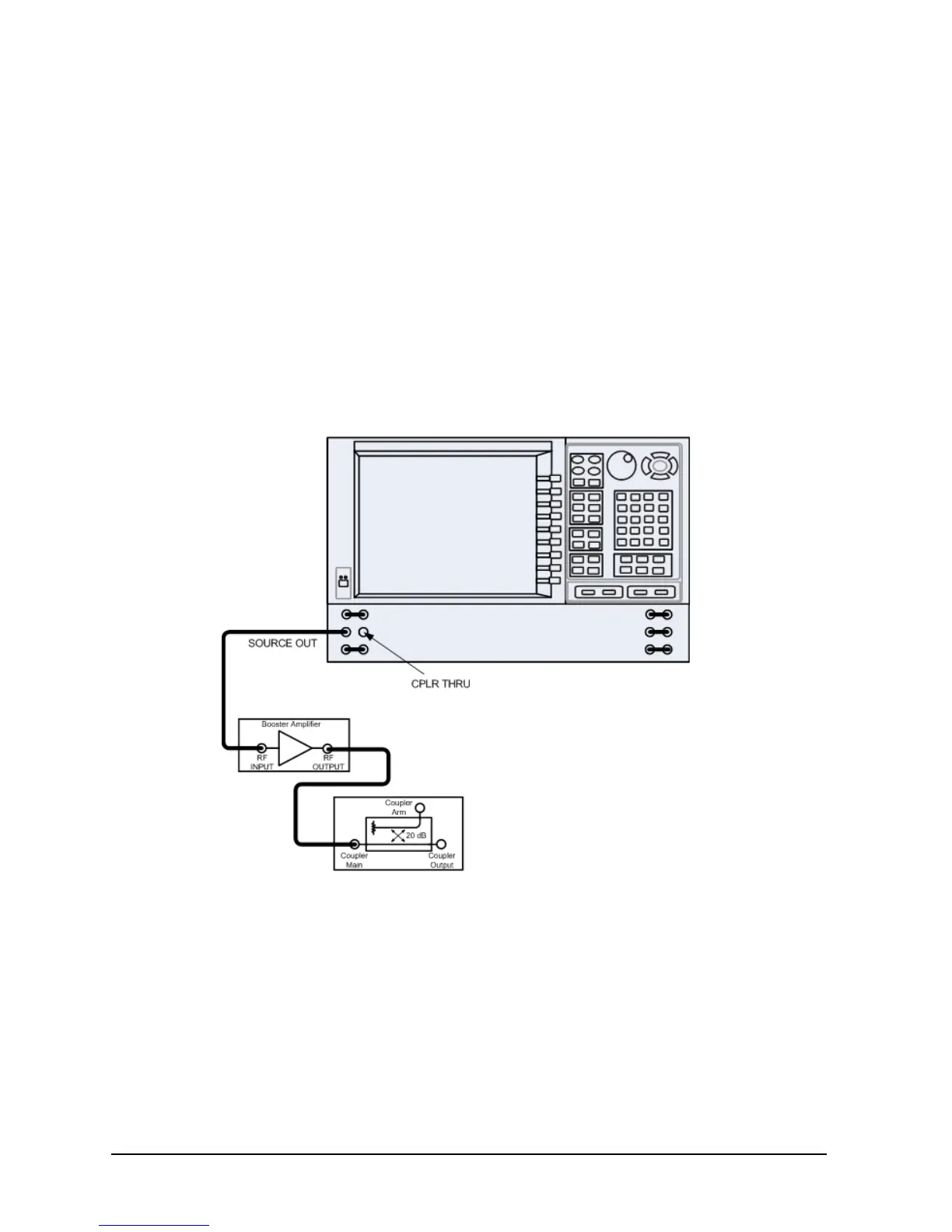
1. If the analyzer is in the standard mode configuration remove the jumper between Port 1
SOURCE OUT and CPLR THRU connector on the front panel, see to Figure 6. This can
also be done for Port 2 if high power measurements are necessary for the reverse
parameters of a device under test (DUT). Two booster amplifiers and two 20 dB
couplers are required for both forward and reverse measurements.
2. Connect the booster amplifier RF INPUT connector to the Port 1 SOURCE OUT
connector on the front panel of the analyzer.
3. Connect a 20 dB coupler (that operates within the frequency range of interest) to the
booster amplifier RF OUTPUT connector.
Figure 6 Booster Amplifier and 20 dB Coupler Connection Setup