22 User’s Guide
E8362/3/4C Option H85
Example: Making High Power Measurements with Option H85
Additional Setup
1. Turn Off the booster amplifier.
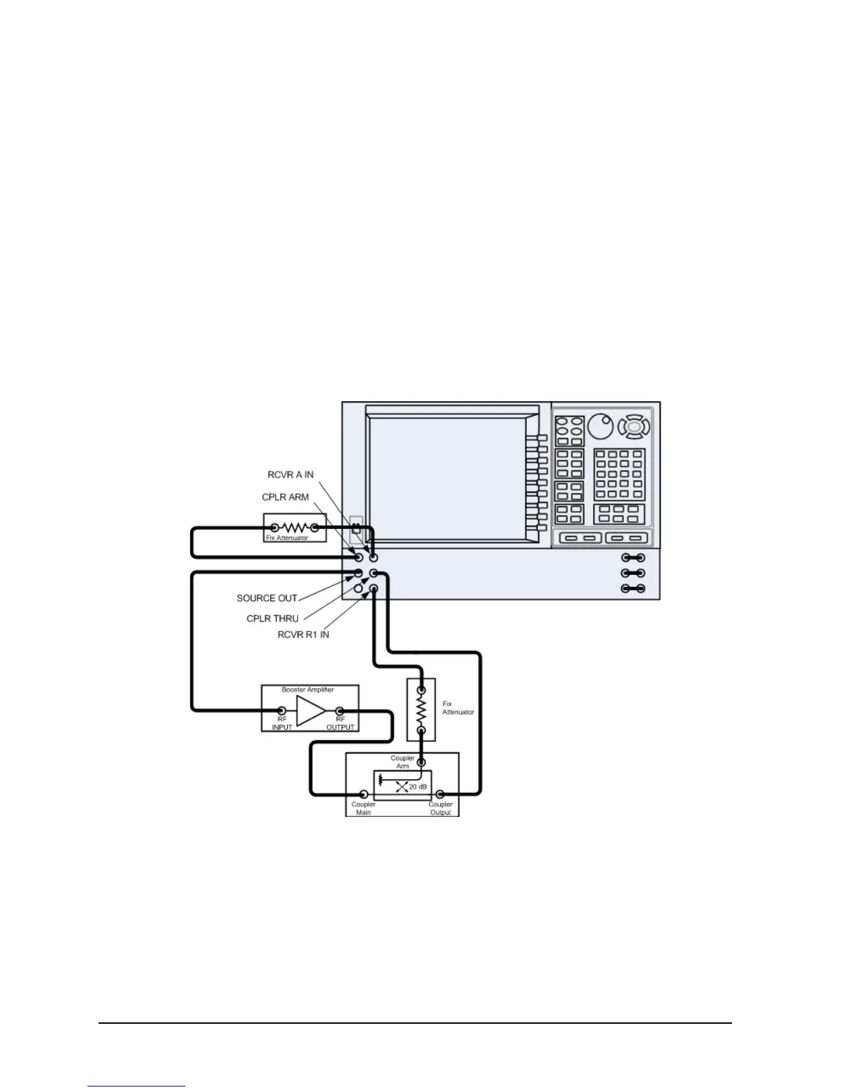
2. Connect the open port of the 20 dB coupler to the Port 1 CPLR THRU connector on the
front panel. This can also be done on Port 2 if reverse parameters high power
measurements are required. Refer to Table 1 on page 4 and Table 6 on page 9.
3. Disconnect the REFERENCE SOURCE OUT and RCVR R1 IN jumper on the front
panel. Connect the coupled arm of the 20 dB coupler (along with any added
attenuation) to the RCVR R1 IN. The same instructions apply to Port 2 with one
exception; disconnect the jumper to RCVR R2 IN if high power measurements are
required for the reverse parameters. Refer to Table 2 on page 5, Table 4 on page 7 and
Table 5 on page 8.
Figure 9 PNA Port 1 Amplifier, Coupler and Attenuator Connections