Service Guide E8364-90026 7-77
PNA Series Microwave Network Analyzers Repair and Replacement Procedures
E8362B, E8363B, E8364B Removing and Replacing the USB Hub
Removing and Replacing the USB Hub
Tools Required
• T-10 TORX driver (set to 9 in-lb)
• ESD grounding wrist strap
Removal Procedure
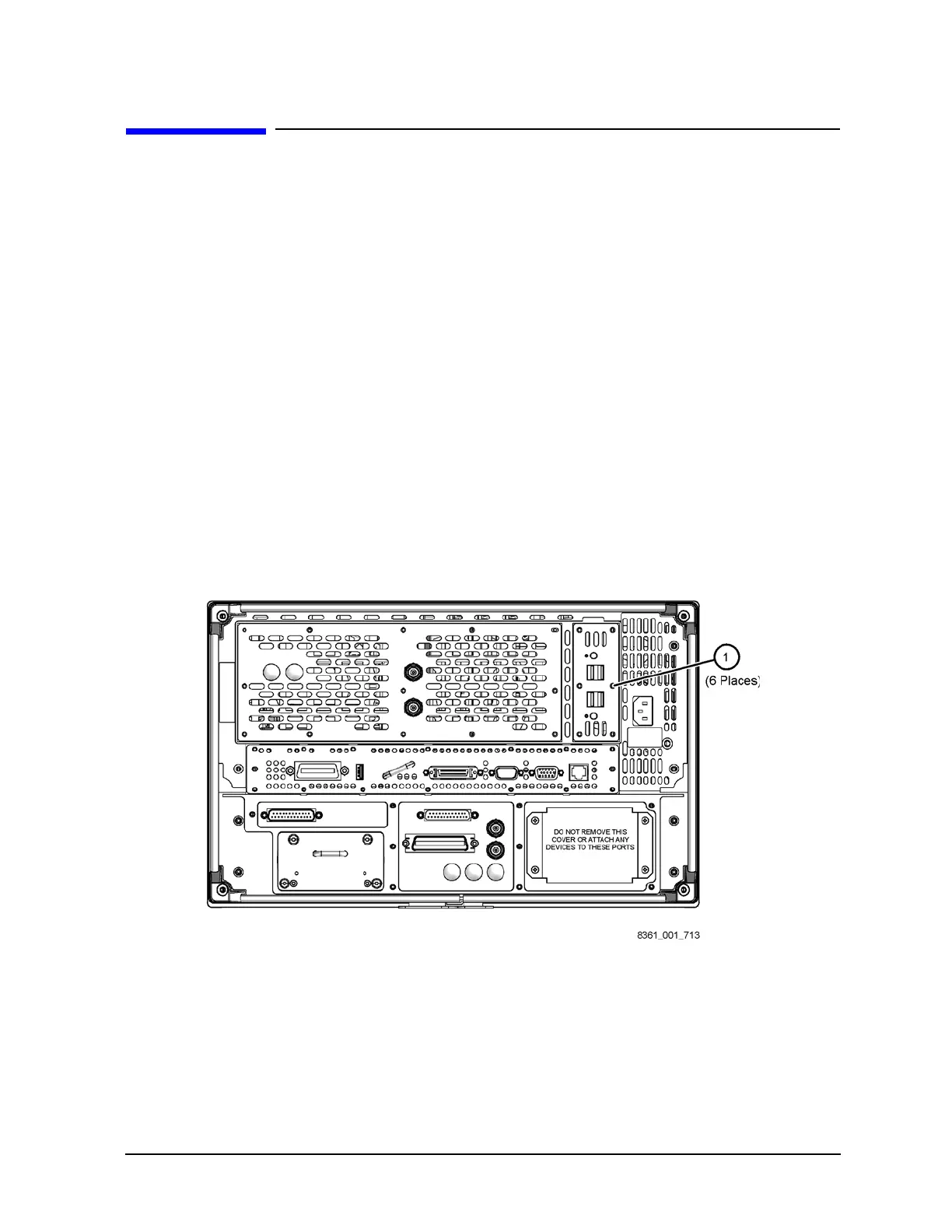
Refer to Figure 7-37 for this procedure.
1. Disconnect the power cord.
2. With a T-10 TORX driver, remove the six screws (item
①) from the USB hub cover
plate.
3. Pull the cover plate away from the analyzer to expose the connecting cable.
4. Disconnect the USB hub cable from the USB hub board.
5. Remove the USB hub from the analyzer.
Figure 7-37 USB Hub Removal
Replacement Procedure
1. Reverse the order of the removal procedure.
2. Perform the post-repair adjustments, verifications, and performance tests that pertain
to this removal procedure. Refer to Table 7-2 on page 7-80.
 Loading...


