8-4 Service Guide E8364-90026
General Purpose Maintenance Procedures PNA Series Microwave Network Analyzers
Error Terms E8362B, E8363B, E8364B
Performing Measurement Calibration
A calibration must be performed to allow the analyzer to calculate the error terms before
they can be used as a tool:
CAUTION
Perform the following procedure only at a static-safe workstation, and wear a
grounded wrist strap.
This is important. If not properly protected against, electrostatic discharge
can seriously damage your analyzer, resulting in costly repair.
To reduce the chance of electrostatic discharge, follow all of the
recommendations outlined in “Electrostatic Discharge Protection” on
page 1-6, when performing the following calibration.
1. Connect a test cable to Port 2.
2. Perform a full 2-port calibration,
FULL SOLT 2-Port. Refer to embedded help in the
analyzer if necessary.
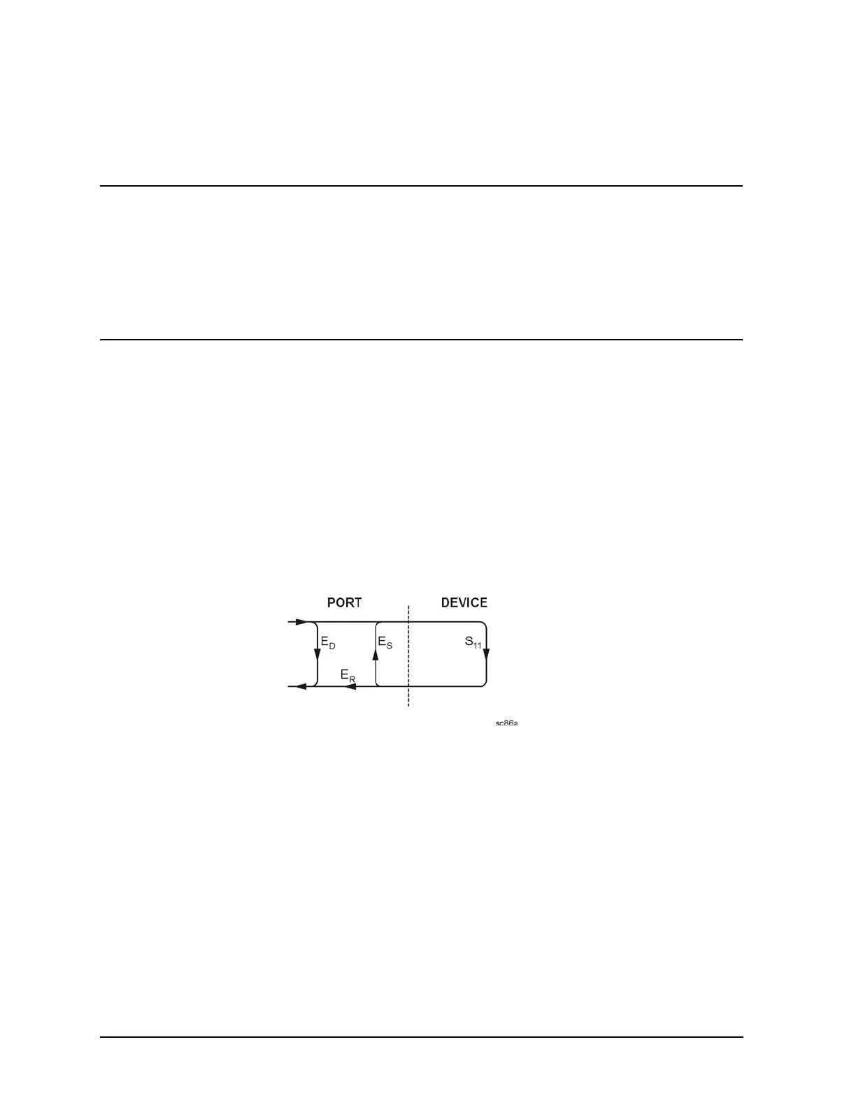
Using Flowgraphs to Identify Error Terms
Flowgraphs are a graphical representation of signal flow through the measurement path.
The flowgraphs in Figure 8-1, Figure 8-2, Figure 8-3, and Figure 8-4 illustrate the error
terms associated with measurement calibration for 1-port, 2-port, 3-port, and 4-port
configurations respectively.
Figure 8-1 Flowgraph of One-Port Error Terms for Port 1
where:
E = Error term
Subscript:
D = Directivity
S = Source Match
R = Reflection Tracking
The error terms are the same for a one port measurement on Port 2 (S
22
).
 Loading...


