26 Chapter 2
Front and Rear Panel Features
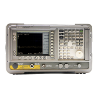
Front Panel Overview
For slow sweeps, the analyzer uses a smooth panning feature which is designed to
move the trace display to the latest function value as the knob is turned. When
center, stop or, start frequency or reference level is adjusted, the signal will shift
right or left or up or down with the rotation of the knob before a new sweep is
actually taken. An asterisk is placed in the message block (the upper right-hand
corner of the analyzer display) to indicate that the data on the screen does not
reflect data at the current setting.
The Numeric Keypad allows entry of exact values for many of the analyzer
functions. You may include a decimal point in the number portion. If not, the
decimal point is placed at the end of the number.
Numeric entries must be terminated with a units key. When a numeric entry is
begun, the menu keys show the units key labels. The units keys change depending
on what the active function is. For example, the units keys for frequency span are
GHz, MHz, kHz, and Hz, whereas the units for reference level are +dBm, −dBm,
mV, μV, and μA.
NOTE If an entry from the numeric keypad does not coincide with an allowed function value (for
example, that of a 12 MHz bandwidth), the analyzer defaults to the nearest allowable
value.
The Step Keys (⇓ ⇑) increase or decrease the active function value. The step size
depends upon the current analyzer measurement. Each press results in a single step
change. For those parameters with fixed values (resolution bandwidth), the next
value in a sequence is selected each time a step key is pressed. Step size is
predictable (e.g., 10% of span for center frequency) and can be set for some
functions (i.e., center frequency). Out-of-range values or out-of-sequence values
will not occur using these keys.
11 VOLUME. The VOLUME knob adjusts the volume of the internal speaker. The speaker
is turned on and off with the
Speaker On Off key in the Det/Demod menu.
12 EXT KEYBOARD. The EXT KEYBOARD connector is a 6-pin mini-DIN connector.
The keyboard can be used to enter screen titles and filenames.
NOTE To avoid damage to the analyzer, always turn off power before plugging a keyboard into
the analyzer.
13 PROBE POWER provides power for high-impedance ac probes or other accessories.
(+15 V, −12.6 V, 150 mA maximum)
14 Return. The Return key accesses the previously selected menu. Continuing to press
Return accesses earlier menus. Return also terminates entry of alpha numeric
functions (e.g., Title).
15 AMPTD REF OUT provides an amplitude reference signal of 50 MHz at –20 dBm.
Agilent EMC models E7402A, E7403A, E7404A, and E7405A only.
16 Tab Keys are used to move around in the Limit editor, the Correction editor.
17 INPUT 50Ω is the signal input for the analyzer.
 Loading...


