Chapter 2 27
Front and Rear Panel Features
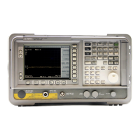
Front Panel Overview
CAUTION When operating in dc coupled mode on analyzers with Option UKB, ensure protection of
the input mixer by limiting the input level to 0 Vdc, +30 dBm.
When operating in ac coupled mode, ensure protection of the input mixer by limiting the
input level to 50 Vdc, +30 dBm.
18 The Next Window key can be used to select the active window in functions which
support split-screen display modes, such as Zone markers. (Refer to “Zone” in the
User’s guide for more information.) In such modes, pressing
Zoom allows you to
switch between the split-screen and full-sized display of the active window.
19 Help. Press the Help key and then any front panel or menu key to get a short
description of the key function and the associated SCPI command. The next key you
press will remove the help window from the display.
20 RF OUT 50Ω for Option 1DN is the source output for the built-in tracking generator.
Option 1DN only.
CAUTION If the tracking generator output power is too high, it may damage the device under test.
Do not exceed the maximum power that the device under test can tolerate.
21 The | (On) key turns the analyzer on, while the Standby key turns most of the analyzer
off. An analyzer alignment is performed (if
Auto Align is on) every time the analyzer
is turned on. After turning on the analyzer, allow 5 minutes of warm-up time to ensure
the analyzer will meet all specifications.
NOTE The analyzer continues to draw power even if the line power switch is in standby. The
detachable power cord is the analyzer disconnecting device. It disconnects the mains
circuits from the mains supply before other parts of the analyzer. The front-panel switch
is only a standby switch and is not a LINE switch (disconnecting device).
 Loading...


