Installation Note E4407-90041
7
Extending the Front Frame
The front frame assembly can be extended from the instrument without detaching any connections or removing the chassis
cover.
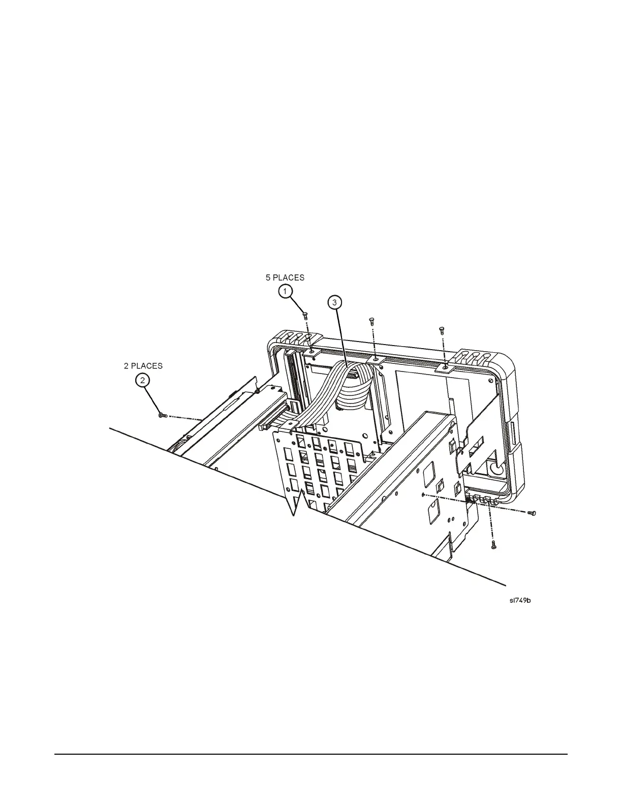
1. Referring to Figure 2, with the instrument still on its face, remove the five screws (1), two on the bottom side and three on
the top of the instrument, that secure the front frame to the RF assembly and chassis cover.
2. Place the instrument with the top side facing up and remove the remaining two screws (2) that secure the front frame
subpanel to the chassis.
3. Slide the front frame forward until it catches on the tabs on the sides of the chassis.
Removing the Front Frame
Figure 2 Front Frame Assembly Removal
1. Disconnect the ribbon cable (3) from the front panel interface board.
2. Carefully pull the sides of the front frame subpanel away from the chassis and over the tabs on the chassis.
3. Slide the front frame forward to disengage from the chassis assembly.
 Loading...


