Installation Note E4407-90041
8
Removing and Replacing the RF Input connector
1. Rotate the analyzer so the right side is resting on the table.
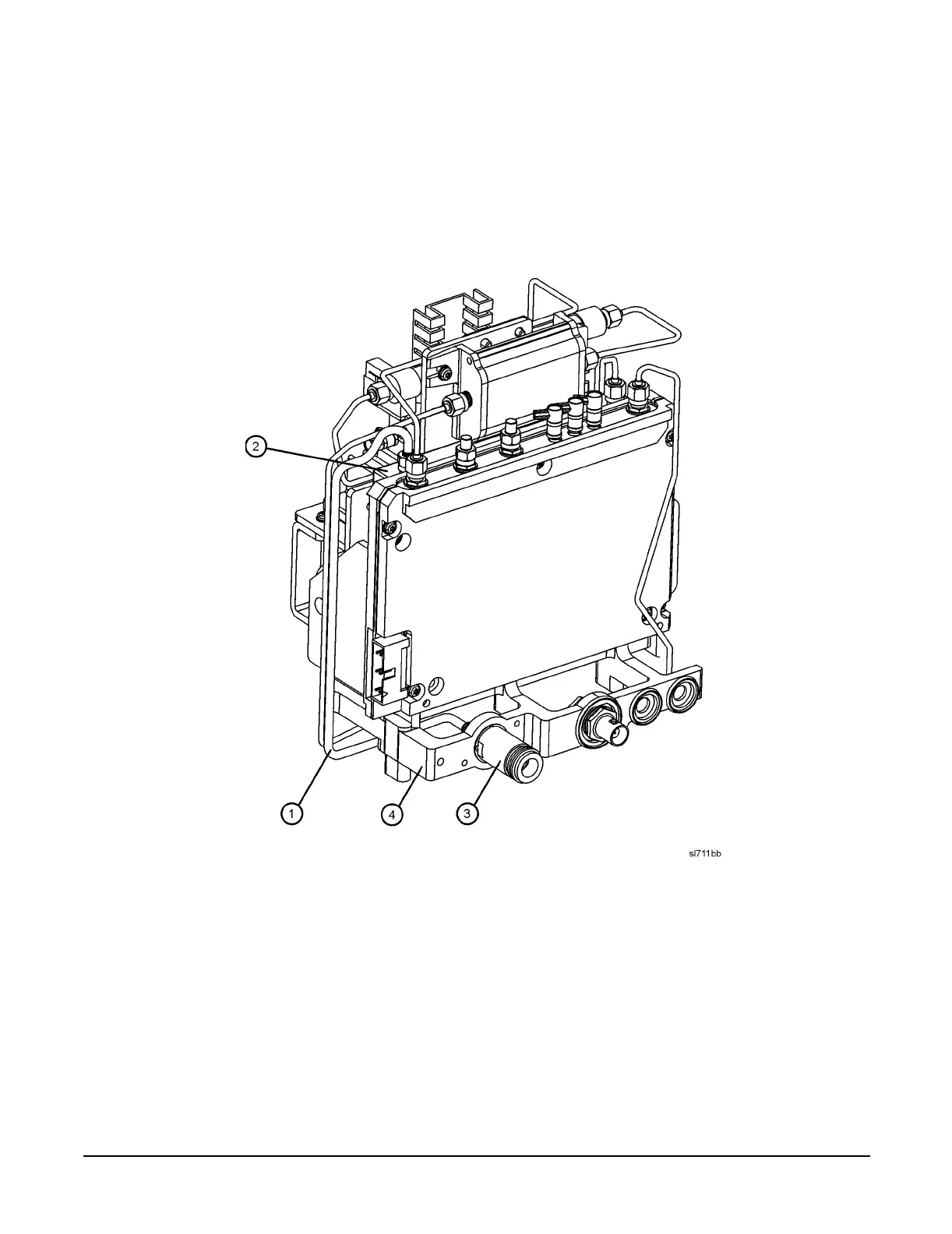
2. Referring to Figure 3, locate W6 (1). W6 is a semi-rigid coax cable connected between the A8A5 input attenuator (2)
and the A8J1 input connector (3).
Figure 3 Replacing the Input Connector and Cable
3. Remove W6 (1) from A8J1 (3), then from A8A5 (2). Discard the removed cable as it will no longer be needed.
4. Remove the A8J1 input connector from the midweb (4).
5. Attach the APC 3.5 mm input connector included in this kit to the midweb (4) using the two 3.0 mm screws provided in
the connector kit.
6. Connect the new W6 semi-rigid cable, included in the kit, between the A8A5 input attenuator (2) and the APC 3.5 mm
input connector (3). Tighten the SMA connectors to 8.5 inch pounds.
 Loading...


