Troubleshooting
ALC
Assembly
(A10)
Troubleshooting
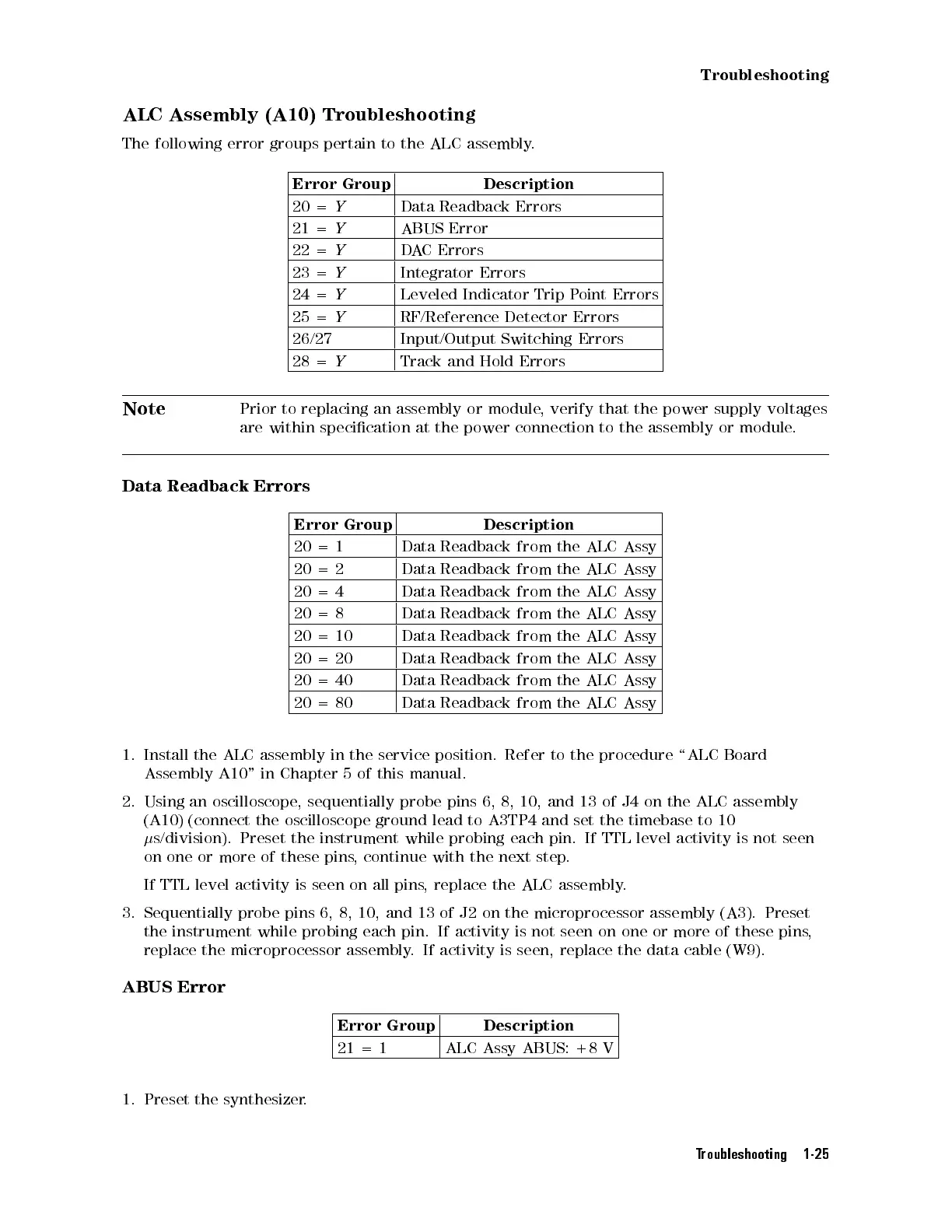
The
following
error
groups
pertain
to
the
ALC
assembly
.
Error Group Description
20 =
Y
Data Readback
Errors
21
=
Y
ABUS
Error
22
=
Y
D
A
C
Errors
23 =
Y
Integrator Errors
24
=
Y
Leveled
Indicator
Trip
P
oint
Errors
25
=
Y
RF/Reference
Detector Errors
26/27 Input/Output
Switching
Errors
28 =
Y
Track and
Hold Errors
Note
Prior
to
replacing
an
assembly
or
module
,
verify that
the power
supply voltages
are
within
specication
at
the
power
connection
to
the
assembly
or module
.
Data Readback
Errors
Error
Group
Description
20 =
1
Data Readback
from
the
ALC
Assy
20
=
2
Data
Readback
from
the
ALC
Assy
20
=
4
Data
Readback
from the
ALC
Assy
20
=
8
Data
Readback
from
the
ALC
Assy
20
=
10
Data
Readback
from
the
ALC
Assy
20
=
20
Data
Readback
from
the
ALC
Assy
20
=
40
Data
Readback
from
the
ALC
Assy
20
=
80
Data
Readback
from
the
ALC
Assy
1.
Install
the
ALC
assembly
in
the
service
position. Refer
to the
procedure \ALC
Board
Assembly
A10"
in
Chapter
5
of
this
manual.
2.
Using
an
oscilloscope
,
sequentially
probe
pins
6, 8,
10, and
13 of
J4 on
the
ALC
assembly
(A10)
(connect
the
oscilloscope
ground
lead
to A3TP4
and set
the timebase
to 10
s/division).
Preset
the
instrument
while
probing
each
pin.
If
TTL
level
activity
is
not
seen
on one or more of these pins
,
continue with the next step
.
If TTL level activity is seen on all pins
, replace the ALC assembly
.
3. Sequentially probe pins 6, 8, 10, and 13 of
J2 on the microprocessor assembly (A3). Preset
the instrument while probing each pin. If activity is not seen
on one or more of these pins
,
replace the microprocessor assembly
. If activity is seen, replace the data cable (W9).
ABUS Error
Error Group Description
21 = 1 ALC Assy ABUS: +8 V
1. Preset the synthesizer.
Troubleshooting 1-25
 Loading...


