Page 8 of 14 MSO8104A-05A
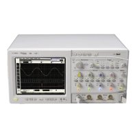
Figure 12
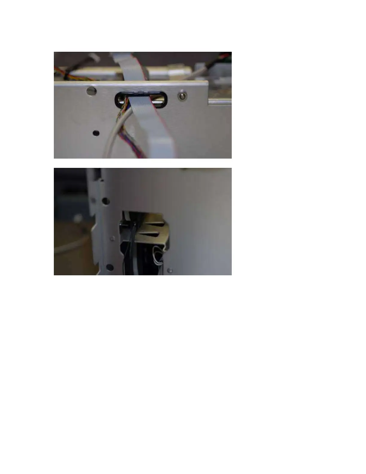
25 Route cables though the chassis holes to prepare to reattach the front Panel assembly to the
frame. (See figure 12 and 13)
Figure 13 and 14
26 Re-install Front Panel with four Torx T15 screws that secure the chassis sides to the front
panel assembly.
When re-assembling, torque the four Torx T15 screws to 18 in-lb.
27 Using a 9/16” nut driver, install five hex nuts that secure the BNC connectors to the front
panel.
When assembling the hex nuts to secure the BNC connectors to the front panel, put the conical side of
the nut toward the front-panel casting. Torque the five hex nuts to 18 in-lb.
28 Reattach the Auto-Probe to the mylar flex cable and pop board back into place.
29 Using new Motherboard Deck “Tray” D8104-60103 and New Motherboard 0960-2689
a Install the six 5 mm port lock screws from the rear panel connectors.
b Install the 5 short Torx T10 screws holding the motherboard to the M880 tray. (See Figure 15)