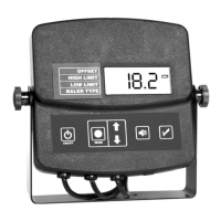
Set Up and Installation
INSTALL DISPLAY MODULE
1. Select a location (on a flat surface) in the tractor cab where the dis-
play can be easily viewed while baling.
2. Using the mounting bracket as a template, mark and drill 3/32”
size pilot holes and secure the bracket with the included sheet
metal screws.
3. Mount the display module to the bracket by adjusting the knobs on
either side of the display.
CONNECT SENSOR AND POWER CABLES
POWER CABLE CONNECTION
1. Locate a positive (+) 12 volt power wire that is controlled by the trac-
tor’s ignition switch or a constant (+) 12 volt supply and connect the
red wire of the power cable.
2. Attach black wire of the power cable to the tractor frame (Negative)
or other negative connection.
3. Plug the power cable connector into the display module’s two pin con-
nector.
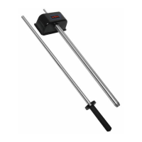
SENSOR CABLE CONNECTION
1. Route the sensor cables from the baler to the cab of the tractor.
2. Locate the 3 pin sensor cable that was previously marked for the cut
side sensor and connect it to the connector on the display module’s
cable marked cut side. Then connect the remaining sensor cable to
the other connector on the display module.
NOTE: On large square balers, there will not be a cut side. This
only applies to small square balers.
NOTE: When choosing a location for the sensors, they must be
placed in an area on the sidewall or tailgate where the hay is in
bale form. Placing the sensors in an area where the hay is still
loose will result in inaccurate readings.
11