Two-wheel tractor agria 3600
5
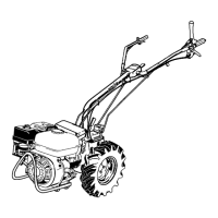
Fig. A
1 Fuel tank
2 Fuel tank cap
3 Toolbox
4 Lower bar
5 Handlebars
6 Latch for lateral and swivel
movements of the steering bar
7 Plug
8 Coupling jaw
9 Lynch pin
10 Latch for implement attachment
11 Reverse locking pin
12 Implement connection with
integrated PTO shaft
13 Ballast carrier and engine safe-
ty bar
14 Engine
15 Gearbox oil filler opening and
dipstick
16 Nameplate
(Ident/machine no.)
(right, in driving direction)
17 Single-wheel brake
18 Wheel flange
19 Transmission oil drain plug
Fig. B
1 Safety lever
2 Notch lever for steering bar
height adjustment
3 Speed control lever
4 Engine stop switch
5 Manual clutch lever
6 Shifting rod for PTO shaft with
rear implement attachment
Gear shifting rod with front im-
plement attachment
7 Gear shifting rod with rear im-
plement attachment
Shifting rod for PTO shaft with
front implement attachment
8 Overdrive shifting rod
9 Stop pawl for wheel switching
10 Hand lever for single-wheel
brake left with rear implement
attachment
Hand lever for single-wheel
brake right with front imple-
ment attachment
11 Hand lever for single-wheel
brake right with rear implement
attachment
Hand lever for single-wheel
brake left with front implement
attachment
12 Latch for lateral and swivel
movements of the steering bar
 Loading...