13
EN
Note
• No more than 1 KINLEY/KINLEY XL and 1 other re-
frigerator/freezer cabinet should ever be connected
to a residual current circuit breaker (RCCB) or a resid-
ual current circuit breaker/miniature circuit breaker
combination (RCBO) for the cabinet circuit (refrig-
eration system).
6.2.3 Residual current circuit breaker/
miniature circuit breaker with overcur-
rent protection (RCBO)
The following RCBOs are permitted:
Character- Rated Trip Type
istic current current
“C” 16 A 30 mA “G”
Note
• Load shedding circuits or cabinet circuits are not per-
mitted as interferences may occur.
7. Commissioning and function
The cabinet should have a minimum temperature of
+16 °C (60.8 °F) before being commissioned.
The glass doors are needed to operate the cabinets
correctly. Open the cabinets only for loading and prod-
uct removal purposes.
The cabinet starts working after a brief delay after the
power is connected.
8. Temperature setting and
monitoring system
Note
• Please adhere to the statutory storage temperature
for your products.
The temperature display shows a temperature inside
the cabinet that does not correlate directly with the
product temperature. Displays up to –25 °C (–13 °F)
are possible, depending on product turnover. Even if
very low temperatures are displayed, the cabinet is not
set too cold because the product temperature at the
stacking limit is warmer than in the air channel.
9. Operating the temperature
controller
The electronic temperature controller on the cabinet
can be operated using the keys (location of the con-
troller is customer-specific).
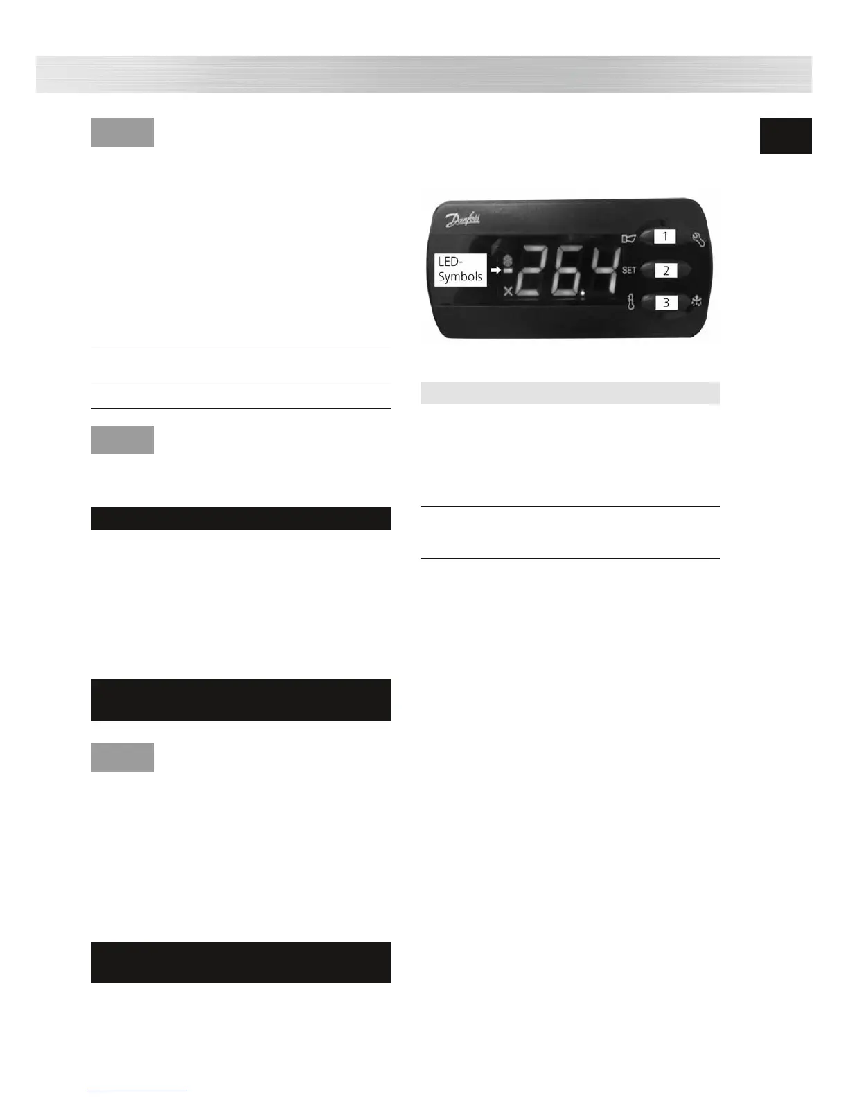
9.1.1 Danfoss electronic controller
Three keys are provided as operating elements and are
used as follows:
Fig. 2: Danfoss controller – controls and displays (symbols)
No. Control Function
1 Top key - Access
Key [1] programming level
- Increase the set-
point/bus address
- Acknowledge alarm
- Call up error code
2 Centre key - Setpoint adjustment
Key [2] - Display and accept
bus address
3 Bottom key - Lower setpoint/bus
Key [3] address
- Start manual
defrost
Note
9.1.2 Adjusting the setpoint
To display the set temperature (setpoint):
Press key [2] briefly.
To raise the setpoint:
Press key [1] briefly.
To lower the setpoint:
Press key [3] briefly.
To add a new entry:
Press key [2] briefly.
9.1.3 Assigning the bus address
The cabinets must be networked with an appropriate
bus cable before address assignment. A terminator
must be fitted for the last participant. The controller
is supplied as standard with bus address “001” ( = a
stand-alone cabinet).
The bus addresses must be assigned starting with 001
to identify several cabinets in the bus system. We rec-
ommend then entering the addresses according to the
actual wiring sequence. A maximum of 240 addresses
are possible.
Instruction
 Loading...