AA 2D 00 00 55, then distance = 002D = 45cm, gesture = 00, no gesture.
AA 36 00 01 55, then distance = 0036=54cm, gesture = 01, gesture.
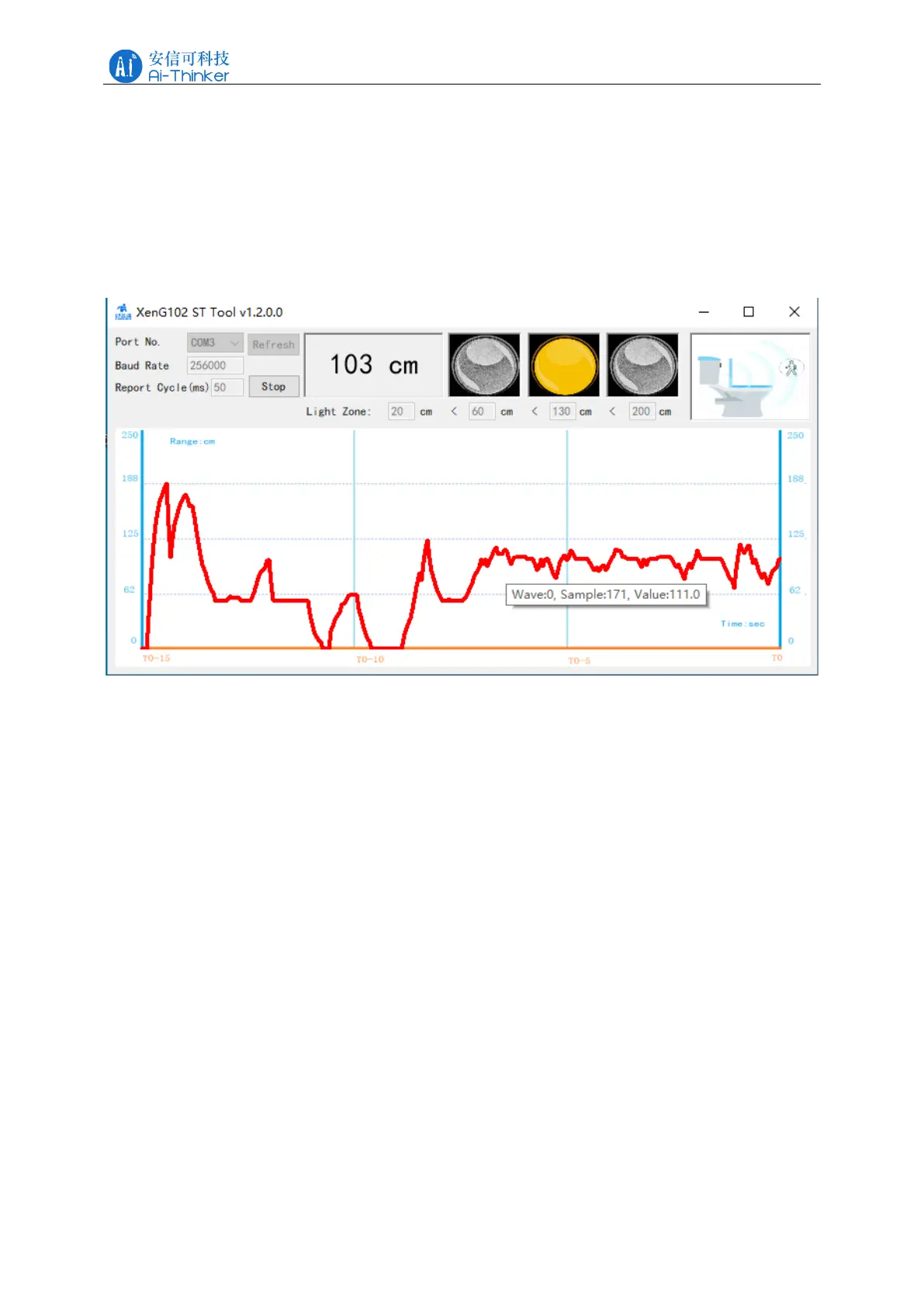
The distance information can be displayed by the host computer tool, as shown in Figure
5-1. The top of the software interface shows the target distance measured by the millimeter
wave radar, the far right is the toilet state, and the red curve below the interface is the real-time
distance waveform.
Figure 5-1 Rd-03E gesture recognition PC tool interface diagram
6 Installation instructions
When installing the module on the bare board, the installation position should be 45cm
higher than the ground, and the placement angle should be 45 upward, as shown in Figure 6-1.
When installing, pay attention to the antenna direction, and the antenna 4 patch direction
should be taken as the horizontal direction.
When the module is installed on the toilet, the recommended installation angle is the same
as that of the bare board installation, which is 45 ° upward.