Rd-03E Gesture Recognition User Manual V1.0.0
Copyright © 2023 Shenzhen Ai-Thinker Technology Co., Ltd All Rights Reserved
3 Hardware Description
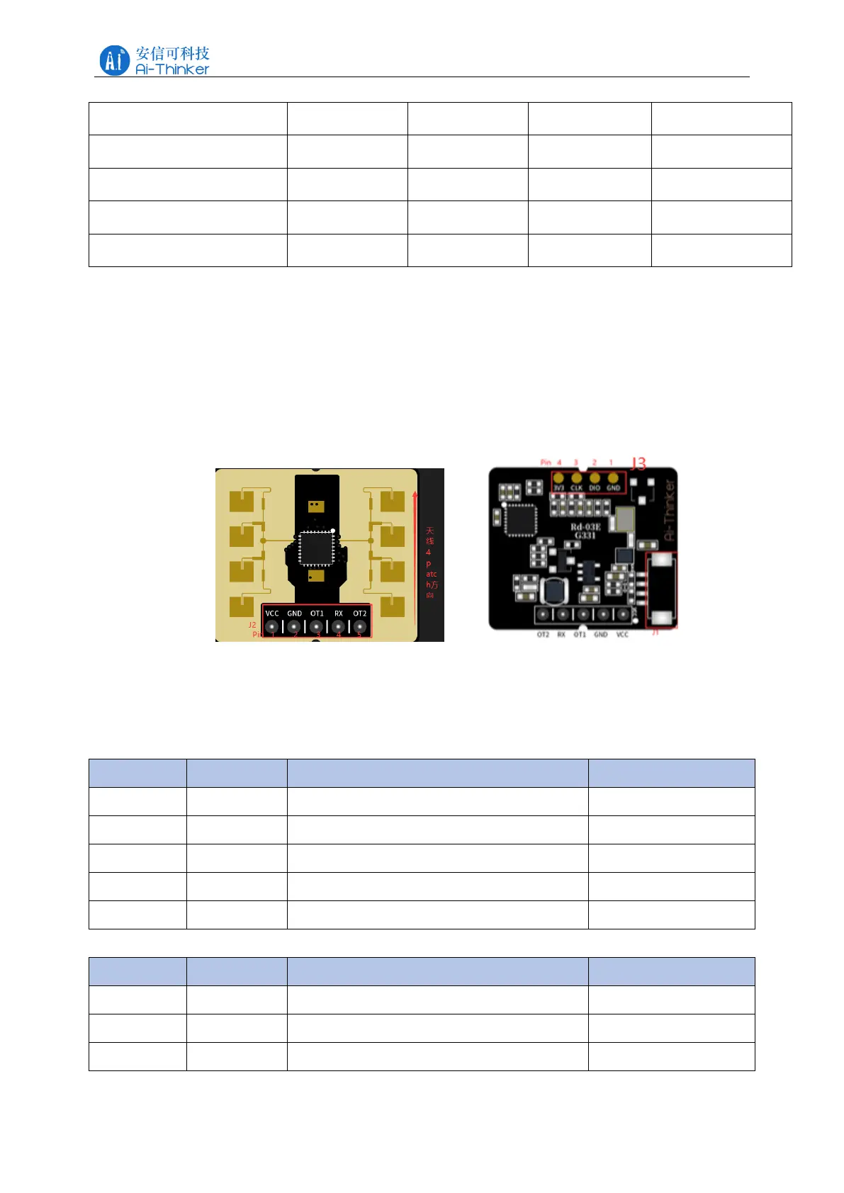
Rd-03E supported hardware is Xen102. Figure 3-1 is a photo of the front and back of the
Rd-03E. Five pin holes J2 are reserved for the Rd-03E hardware (no pin is provided at the
factory), which are the power supply and communication interface. The MCU burning port is
called J3. Please connect according to the corresponding pin name when burning. (J1 is
reserved for USB interface, which is not introduced in this document for the time being.)
(a)front (b)back
Figure 3-1 Rd-03E hardware physical diagram
The pin descriptions of J2 and J3 are shown in Table 3-1 and Table 3-2.
Table 3-1 J2 Pin Description