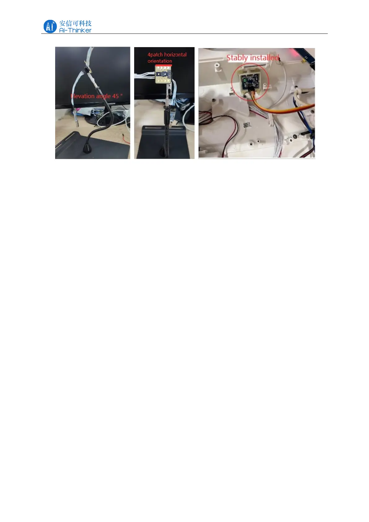
Figure 6-1 Schematic diagram of Rd-03E module installation
If the radar requires an enclosure, the enclosure must have good permeability in the 24
GHz band and must not contain metal or materials that shield against electromagnetic waves.
Refer to the Millimeter Wave Sensor Radome Design Guide for additional radar enclosure
considerations.
When installing, ensure that the installation position of the sensor is firm and stable,
because the shaking of the radar itself will affect the detection effect. Make sure that there is no
movement or vibration on the back of the radar. Due to the penetrating nature of radar waves,
the back flap of the antenna may detect moving objects on the back of the radar, thus
interfering with the detection. A metal shield or a metal back plate can be used to shield the
back flap of the radar to reduce the impact of objects on the back of the radar.
When there are multiple 24 GHz band radars in the installation space, please do not face the
beams and try to stay away from each other to avoid possible interference.
7 Detection range
After the module is installed, take the module position as the center of the circle, the
detection angle of H plane is within ± 40 °, and the detection angle of E plane is within ± 20 °
(the directions of H plane and E plane of the radar are shown in Figure 7-1). The power
diagram of the radar is shown in Figure 7-2, in which: the angle range of moving human body
recognition is ± 20 °, and the distance range is 0.3~2.2 m fan-shaped area; the angle range of
gesture recognition and micro-motion human body detection is ± 30 °, and the distance range is
0.5~1 m fan-shaped area. The range of radar gesture recognition in the toilet application is
shown in Figure 7-3.