-5- -6-
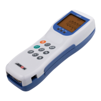
Nomenclature
Descriptionofthecomponentdevices
ComparatorjudgmentLED
PowerON/OFF
ENT
FUNC
PRT
Printeroutput
connector
I/Oconnector
USBconnector
MEMO
ZERO
PEAK
TRACK
Measuringshaft
Display
Aforceisdetectedbythispart.
Donotapplyaforceexceedingtheallowablerangetothe
measuringshaft,asitmaycausethegagetofail.
Showstheusersettingmodeandmeasurementresults.
Usedtoturnthepoweronandoff.
Usedtoselectausersettingmodeandmakesetting.
Usedtoentertheusersettingmodeorreturntothe
measurementscreenfromtheusersettingmode.
Pshownlitorflashinginthedisplayindicatesthepeak
mode.Whenitisnotshown,themodeisthetrackmodeand
thedisplayconstantlyshowsthevalueofaforceappliedto
themeasuringshaft.
Usedtoresettheindicatedvaluetozero.
Usedtooutputtheindicatedvaluetoaprinter.
Thegagemustbeconnectedtoaprinterwithanoptional
cableinadvance.
Eachtimethekeyispressed,theindicatedvaluewillbe
storedinthememory.
Normallythisisusedtochangetheunitsofmeasurement.
UsedtochangethemodeNo.intheusersettingmode.
WhenthegageisconnectedtoaDigimaticMiniProcessor
DP-1VRorLinerThermalPrinterBL2-58SNWJCwithan
optionalcable,measuredvaluescanbeprinted.
ConnecttheincludedACadapterMODEL-780andUSBcable
ModelRZ-USBtochargethegage.AlsobyusingtheUSB
cableModelRZ-USB,thegagemaybeconnectedtoaPCto
sendandmanagedata.
①Measuringshaft ……
②Display…………………
③ ON/OFF ……………
④ ENT …………………
⑤ FUNC ………………
⑥ …………
⑦ ZERO ………………
⑧ PRT …………………
⑨ MEMO ………………
⑩ ≫key………………
⑪
≪
key………………
⑫
Printeroutputconnector
……
⑬I/Oconnector
⑭USBconnector……
PEAK
TRACK
×1000
Kgf
N
lb
PHMC
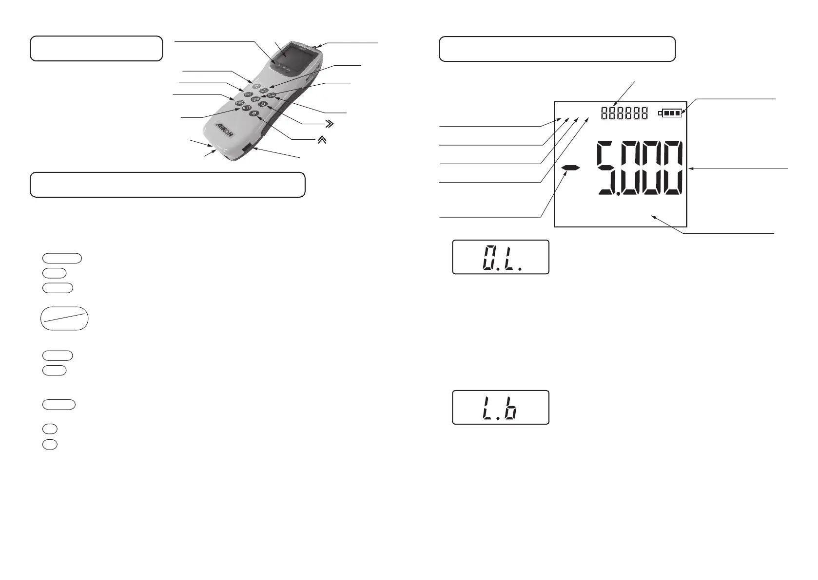
DescriptionoftheDisplay
Overload
Batterylevellow
Thisisasubdisplayforsettingandindicatesthetensile
peakvalueandavaluewhenthecontactisoff.
Indicatestheremaining
batterycharge.
Showsthepresentunitof
measurement.
Lights/flasheswhenthepeak
valueisbeingindicated.
Lights/flashesintheexternal
contactholdmode.
Lightsinthecomparator
settingmode.
Lightswhendataismemorized.
Theminussignisshownwhen
acompressiveforceisindicated.
Indicatesthemeasured
forcevalue.
Forabout3secondsafter
thepoweristurnedon,the
max.forcevalueusedand
thesoftwareversionare
shown.Duringmeasurement,
ameasuredvalueisshown.
Lowbattery(L.b)
Whentheremainingbatterychargedropsbelow5%,
thedisplaywillshowL.b.andameasuredvalue
alternatelyandthewarningbuzzerwillsound.When
itdropsbelow3%,thepowerwillbeforcedtobe
turnedoff.
Ifyouturnonthepowerinthisstate,thepowerwill
beturnedoffafterseveralseconds.
Whenthepowerison,turnitoff.Thenconnectthe
includedACadapterandUSBcableandchargethe
batteries.Normallychargingwillbecompletedin
about4.5hours,butthechargingtimemaybecome
longerslightlydependingontemperatureandother
environmentalconditions.
Overload(O.L.)
Whenaforceexceedingabout110%ofthe
a llowablemaximumforceisappliedtothe
measuringshaft,thedisplaywillshowO.L.anda
measuredvaluealternatelyandthewarningbuzzer
willsound.Ifthishappens,immediatelystop
applyingaforce.
Continuingtheapplicationofaforcetothe
measuringshaftwilldamagetheforcesensoror
deterioratetheaccuracy.
※Iftheforcesensorisbroken,itmustbe
replaced/repairedandforcecalibrationmustbe
performed.
 Loading...