17
• TRIGGER/LOCAL key. Used to enter the Trigger menu where the instrument trigger parameters
may be specified. This key is also used on a dual channel instrument to return to local from
remote mode.
• UTILITY key gives access to menus for a variety of functions such as SYNC OUT set−up,
power−up parameters and error message settings.
• STORES key allows access to the built in storage for waveforms and set-ups and to a connected
flash drive.
• KNOB and left and right cursor keys. Used during numeric entry. The left and right keys move
the edit position left or right and the knob increments or decrements the value of the selected
digit.
• The HELP/ LOCAL key, available on a single channel instrument, gives direct access to the
complete help system. On a dual channel instrument the help system is accessed from the Utility
menu. However, context sensitive help can be obtained for any key, including soft-keys, by
holding the key down for 2 seconds. This key is also used on a single channel instrument to
return to local from remote mode.
Further explanations will be found in the detailed descriptions of the generator’s operation.
Display
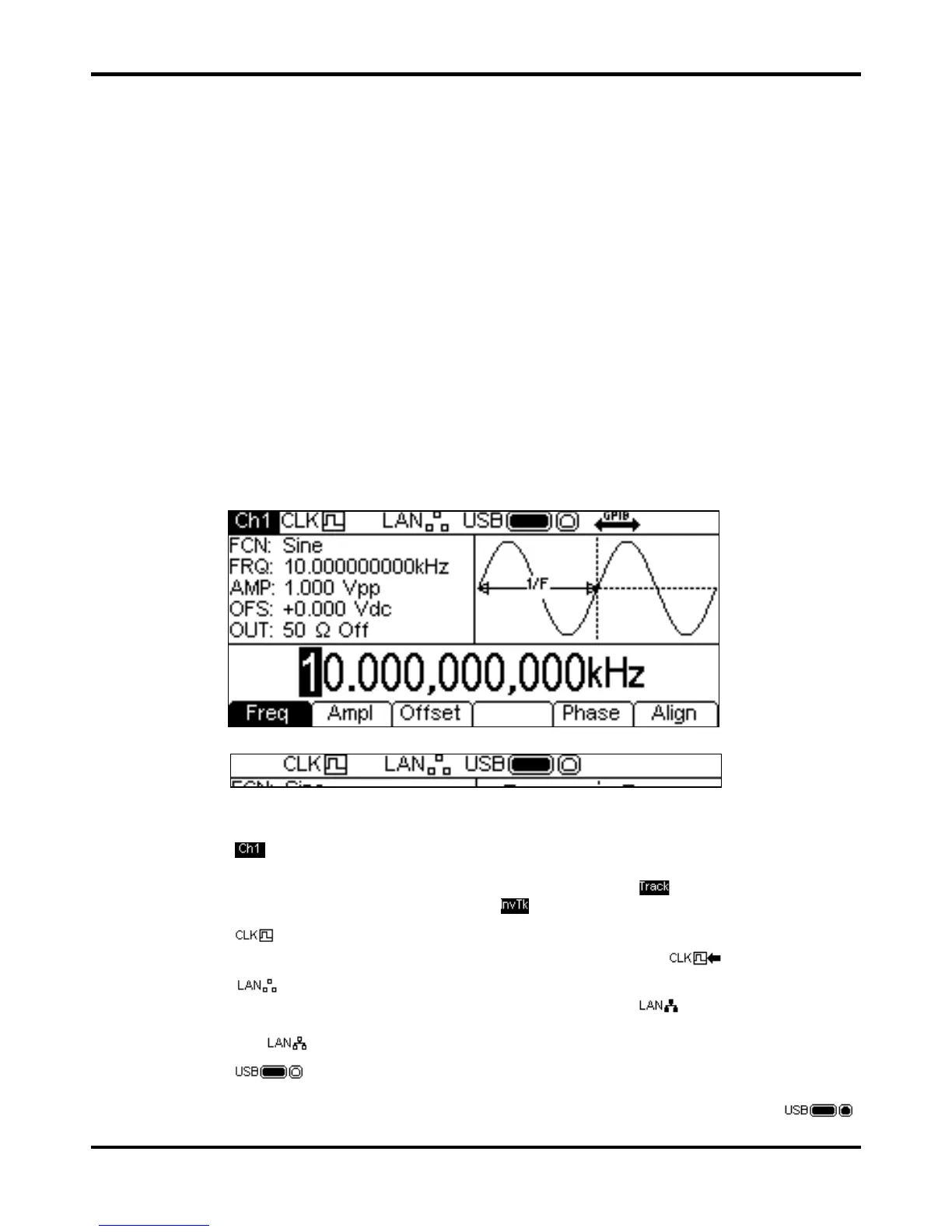
All parameter settings are displayed on the 256 x 112 pixel backlit liquid crystal display (LCD). The
most common type of display layout is shown below:
The Status Line indicates the status of the instrument as follows:
• The
field is blank on a single channel instrument. On a dual channel instrument it
indicates which channel is currently selected for editing. As shown above, channel 1 is
selected. If the channels are Tracking the field will change to
. If the channels are
Tracking with inversion the field will show
.
• The
field indicates which clock source the instrument is using. As shown, the clock
source is internal. If the source is external the field will change to
.
• The
field indicates the status of the Local Area Network interface. As shown, there is
no LAN connection. When connected the field will change to
. While a connection is
being established the indicator will flash. If the Lan is connected but not enabled the field will
show as
. See the remote control sections for more detailed information.
• The
field indicates the status of the two USB ports. The left icon is the flash drive
and the right icon is the device port for instrument remote control. As shown there is a flash
drive inserted but the device port is idle. With the device active the field will show
.
Activity on either port will cause the corresponding icon to flash.


 To Next Page