18
• The Field shows the GPIB port status. As shown, the port is disabled. When the port
is enabled the field will show
. During GPIB remote control the icon will flash. If GPIB is not
fitted to the instrument the field will be blank.
• The area on the extreme right will show
REM when the instrument is in remote state with
the keyboard locked. To regain keyboard control press the LOCAL key.
Below the Status Line are two boxes which show how the instrument is currently operating.
• The Parameters Box on the left shows the settings of all the carrier waveform parameters
for the selected channel. These include
FCN (function), FRQ (frequency), AMP (amplitude),
OFS (offset) and OUT (output state). This information will be updated as the parameters are
edited. While any of the modes, for example Sweep, are being edited the fields will temporarily
change to show the additional parameters for that mode. See the respective sections on mode
editing.
• The Graph Box on the right shows a representation of the waveform which the instrument is
generating on the selected channel. The parameter currently being edited is indicated by arrows.
The lower part of the display contains the Edit Box which shows the value of the parameter
currently being edited on the selected channel. This will be a numeric value or a parameter string.
Under the Edit Box are the current Soft-key Labels which change as editing proceeds.
The Status Line and the Soft-key Labels are always shown on the LCD. The section between these
areas will sometimes change in appearance, for example when displaying help.
A Pop-up Box may also appear to provide error or warning messages or to give other information to
the user. See Appendix 1: Information, Warning and Error Messages for a full list of messages.
Editing Principles
The instrument parameters are edited using the keyboard in conjunction with the Soft-key Labels
and the Edit Box.
Generally, the required parameter is selected by pressing waveform keys, modulation keys or soft-
keys or a combination of these to show the parameter in the Edit Box. The parameter is then edited
using the numeric keys, the soft-keys, the knob and cursor keys or a combination of these.
Example 1: Press the SQUARE key to select square-wave then press the
Duty soft-key to select
the square-wave duty cycle parameter which will show in the Edit Box. Now use the numeric keys
and Soft-keys to change the parameter as described in Numeric Editing.
Example 2: Press the SINE key to select sinewave then press the MOD key to turn on modulation.
Press the
Type soft-key to select the modulation type parameter. Now use the soft-keys to select
the required type from
AM, FM, PM, FSK, SUM or BPSK.
Example 3: Press the ARB key followed by the
Params soft-key then the Load soft-key then the
BuiltIn1 soft-key. Now select one of the built in waveforms from the soft-keys. The Edit Box
will show the loaded waveform.
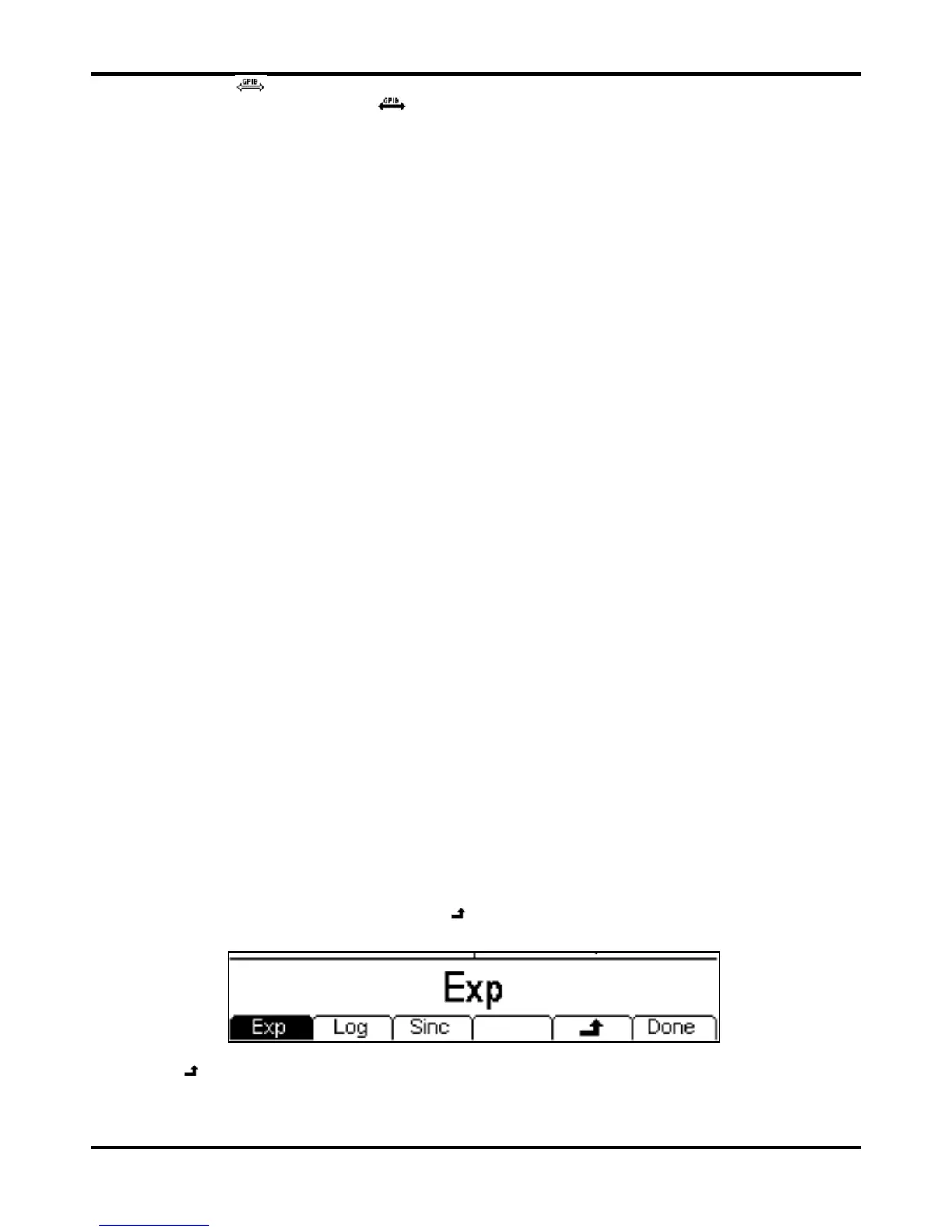
In example 3 notice the last two soft keys
and Done. These keys often appear when editing
and they always perform the same function.
The
key is known as BACK and will move the soft-key labels and Edit Box up one level in the
hierarchy; in this example the status will go back to just before the BuiltIn1 soft-key was pressed.
The
Done key will move back to the top level in the hierarchy; in this example the status will go
back to just after the Arb key was pressed.


 To Next Page