Do you have a question about the Aim ARINC825 and is the answer not in the manual?
Provides an overview of the AMC825-2/4 PMC-CAN interface board with up to 4x CAN and optional ARINC protocol and IRIG-B.
Explains the structure of the AMC825 Hardware Manual, detailing its sections on introduction, installation, and technical data.
Lists documents relevant to the AMC825 hardware, including product-specific AIM documents.
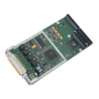
Explains connections to external devices and provides a PCB view of the AMC825-2/4.
Describes the 6 green LEDs on the front panel of the AMC825-2/4 and their functions.
Details the pin assignment for the X400 (DSUB25 male) I/O connector and signals.
Describes the PMC connectors (Pn1, Pn2, Pn4) used for PCI interface and power supply.
Provides specifications for power supply, connectors, temperature range, humidity, dimensions, and weight.
Details specifications related to the PCI bus, including host bus, PMC spec, master capability, data bus, and clock rate.
Details the number, controller, physical interface, electrical isolation, and bus termination for CAN interfaces.
Describes the analogue and digital IRIG-B input types, coding, and the controller.
Provides a glossary of acronyms used throughout the AMC825 Hardware Manual.
| Brand | Aim |
|---|---|
| Model | ARINC825 |
| Category | Computer Hardware |
| Language | English |