AMC825 Hardware Manual 1
1 INTRODUCTION
1.1 Overview
The AMC825-2/4 is a PMC-CAN interface board with up to 4x CAN and optional ARINC
protocol and IRIG-B.
Krypto
Chip
4 x
CAN Core
with Timestamp
8-Bit
Microcontroller
(8051)
1x IRIG-B
FPGA
Xilinx Spartan-3E
(32-Bit Microcontroller
MicroBlaze Option)
IRQ A
PCI Bridge
PLX PCI9056
Bus Master
Capability
PMC
Connector
Pn4
PMC
Connectors
Pn1, Pn2
RAM
(Option)
IRIG-B Input
RS-422
compatible
IRIG-B
RTC
Electrical Isolation
DC/DC
Converter
Physical
CAN Layer
ISO11898-2
CAN
and IRIG-B
Electrical Isolation
CAN
DSUB25
(X400)
4x CAN Interface
CAN
CAN
CAN
IRIG-B Input
Physical
IRIG-B Layer
RS-422
compatible
Physical
IRIG-B Layer
analog
IRIG-B
IRIG-B
IRIG-B
PMC
Front Panel
A/D
Converter
6 LEDs
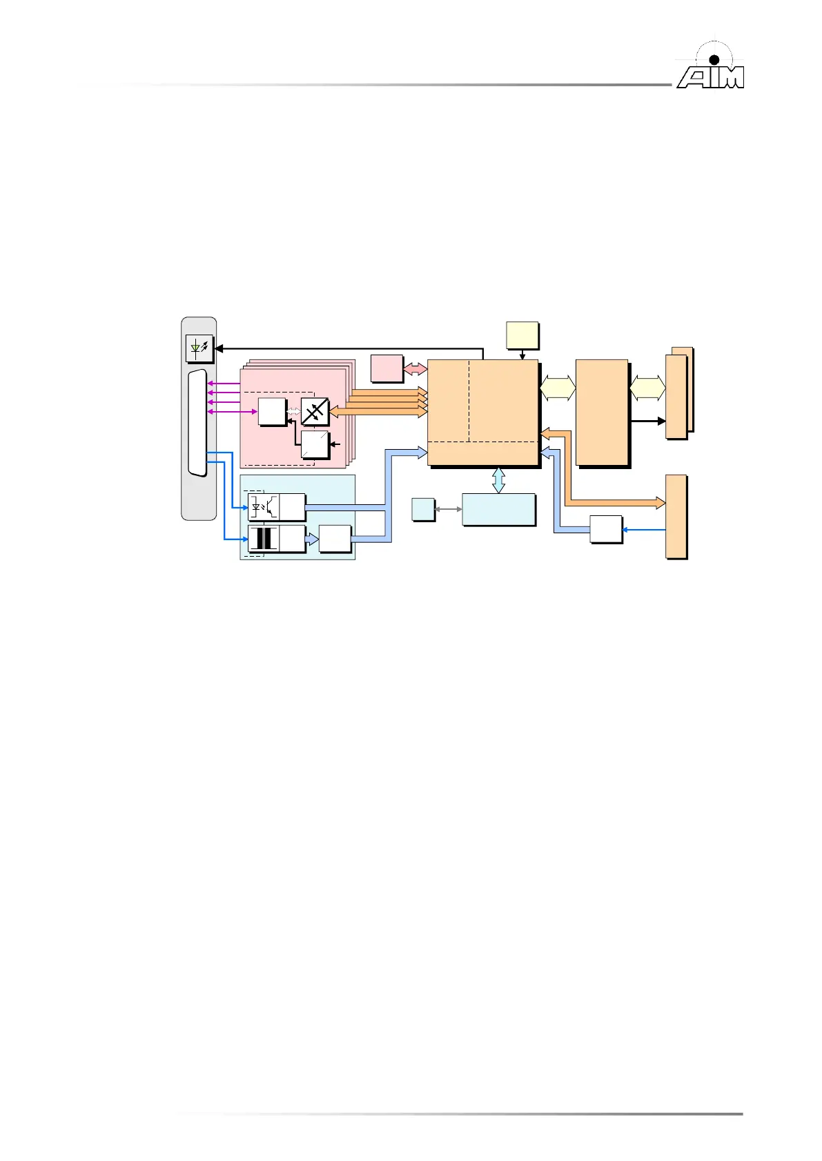
Block Diagram of Standard PMC-CAN/400-4 (Order No.: C.2047.01)
optional FPGA-IO
The AMC825 features four electrically isolated CAN High-Speed interfaces according to
ISO 11898. Local data control and management is controlled by an FPGA. Optional the FPGA is
available with integrated 32-bit soft microcontroller (MicroBlazeTM).
The AMC825 provides high resolution hardware timestamps.
The IRIG-B interface offers inputs for analogue or RS-422 compatible IRIG-B coded signals at
the front panel. Both are electrically isolated.
Additionally a digital input (RS-422 compatible) for IRIG-B is available at the PMC connector
Pn4 (without electrical isolation).
IRIG-B evaluation is controlled by an additional microcontroller.
For the 25-pin DSUB connector in the front panel an adapter cable to 9-pin DSUBs for CAN and
IRIG-B (analogue and RS-422 compatible) is available.