7
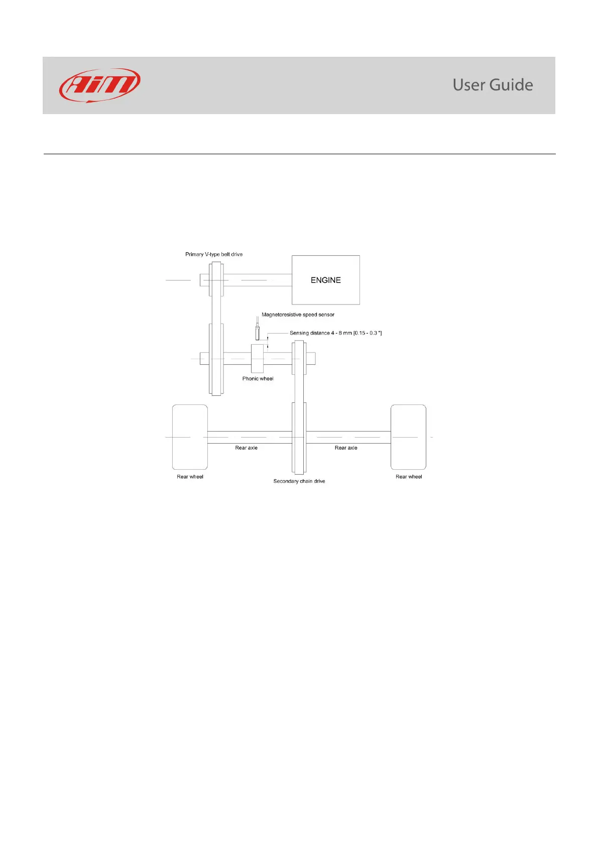
3.5 – Installing the speed sensor
To sample the dragster speed a magneto-resistive speed sensor (part number XSMSNVB301) is to be installed at a 4-8 mm
distance from the phonic wheel (part number DNKTRF660) that is to be installed on the jackshaft (3/4” diameter) moved by the
clutch. The movement of jackshaft and wheel are related to the crown/pinion ratio.
The scheme below shows the layout of the installation.
To correctly install the speed kit, follow these steps:
• remove the pinion and insert the phonic wheel (internal diameter ¾”) on the jackshaft.
• fix the phonic wheel to the jackshaft screwing the nut.
• install the magneto-resistive speed sensor on a self-made bracket; please remember that sensing distance – the distance
between the sensor and the phonic wheel – is to be 4-8mm (0.15”-0.3”)
• plug the speed sensor male connector in the 4 pins Binder 712 female connector rear of MyChron5 660 highlighted here
below.
 Loading...