– 8 –
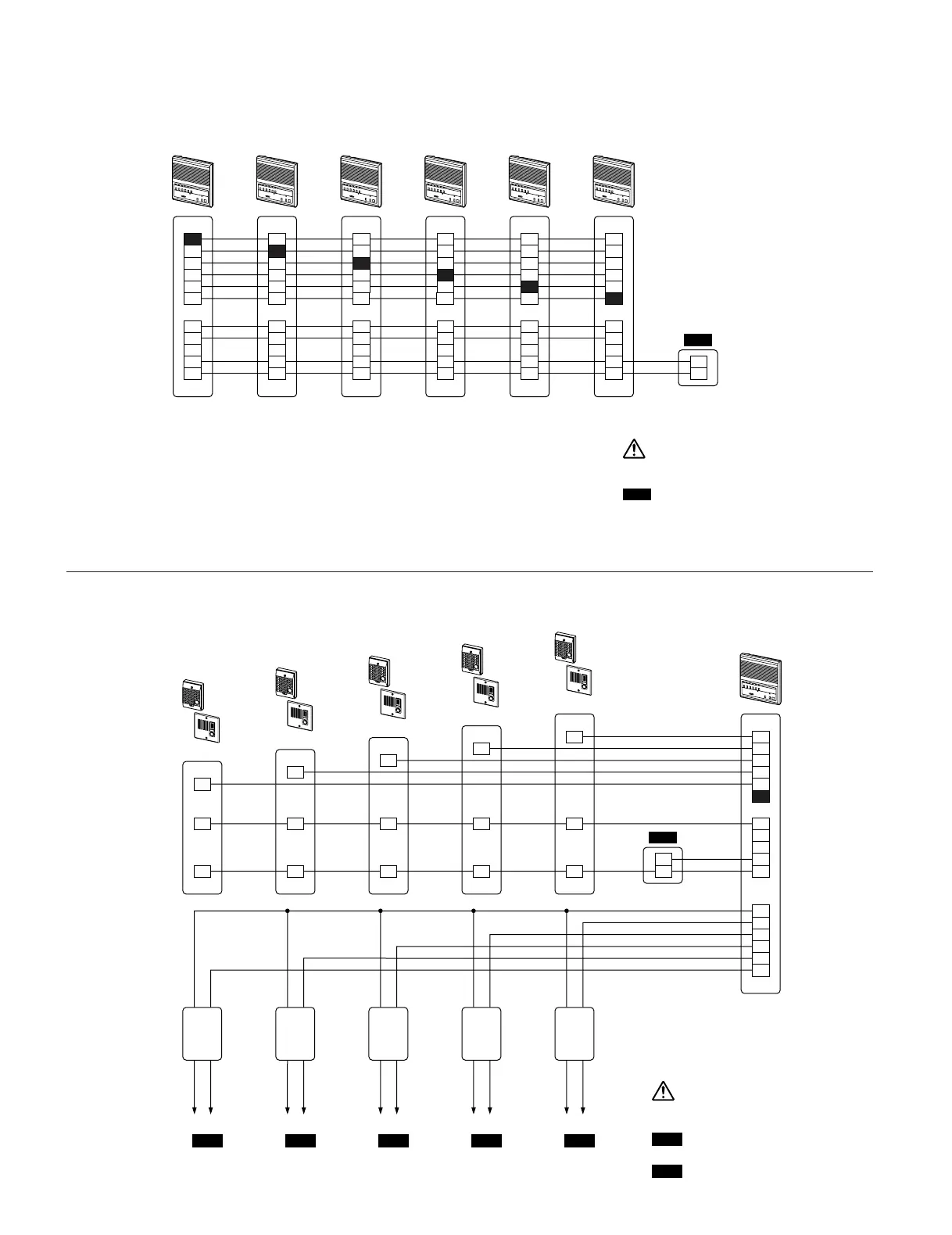
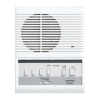
Six LEF-5's
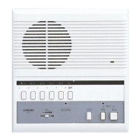
One LEF-5 with Five Door Stations
: PS-1225UL, PS-1225S,
PS-1215DIN
PS12
: PT-1210N in USA or AC trans.
PT
PT PT PT PT PT
: PS-1225UL
PS-1225S
PS-1215DIN
PS12
5
3
2
C
R
E
Y
+
–
+
–
4
LEF-5 #1
1
5
3
C
1
R
E
Y
+
–
4
LEF-5 #2
2
5
C
2
1
R
E
Y
+
–
4
LEF-5 #3
3
5
3
2
1
R
E
Y
+
–
C
LEF-5 #4
4
C
3
2
1
R
E
Y
+
–
4
LEF-5 #5
5
5
3
2
1
R
E
Y
+
–
4
LEF-5 #6
C
+
–
5
3
2
1
R
E
Y
+
–
LL
K1
K2
K3
K4
K5
4
LEF-5
C
1
E
–
1
E
–
1
E
–
E
–
1
1
E
–
Yellow (2)
To Strike
&
To Strike
&
To Strike
&
To Strike
&
To Strike
&
Black (2)
RY-PA
Yellow (2)
Black (2)
RY-PA
Yellow (2)
Black (2)
RY-PA
Yellow (2)
Black (2)
RY-PA
Yellow (2)
Black (2)
RY-PA
Remove the shorting link between
“E” and “
-
” terminals at all the LEF
master stations.
3 conductors is recommended
for door station wiring. If 2
conductor wire is used, the
shorting link between “E” and
“
-
” terminals must remain
attached on all units. This
method can be used only in
single master systems.
PS12
PS12
Note: This is an all master system.
When one master calls another
master, the person at the called
master responds hands free. There
is no station LED indicating which
master station has called.
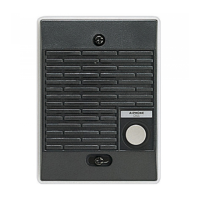
LE-D or LE-DA
LE-D or LE-DA
LE-D or LE-DA
LE-D or LE-DA
LE-D or LE-DA