Do you have a question about the Air Liquide SAF-FRO PRESTOTIG 310 AC/DC and is the answer not in the manual?
| Input Phases | 3 |
|---|---|
| Welding Current Range (TIG) | 5 - 310 A |
| Output Current Range | 5 - 310 A |
| Control Type | Digital |
| Protection Class | IP23 |
| Frequency | 50/60 Hz |
| Input Current | 16 A |
| Efficiency | 85% |
| Power Factor | 0.93 |
| Type | Inverter |
| Welding Processes | TIG, MMA |
| Input Voltage | 400 V |
| Welding Current Range (MMA) | 10-260 A |
| Duty Cycle | 60% at 310A, 100% at 240A |
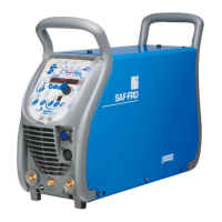
Overview of the PRESTOTIG 240/310 AC/DC welding machines and their primary purpose.
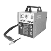
Identifies and locates components and connection points on the machine's front, back, and setting panels.
Machine and accessory technical data including power, dimensions, and standards.
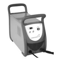
Physical specifications of the welding machines and associated coolers.
Instructions for safely unpacking the welding equipment and initial placement considerations.
Details on correctly connecting the power source to the electrical supply and gas system.
Guides on connecting welding torches, ground clamps, and remote controls.
Step-by-step guide on how to power on and prepare the welding machine for use.
Overview of the different welding processes supported (MMA, TIG AC/DC, pulsed, spot, etc.).
Electrode selection/prep, AC/DC, parameters, striking methods, and AC TIG specifics.
Guidance on using electrodes for MMA welding with the machine.
Instructions for COMPOTIG, THIN, PULSE, SYNERGIC PULSE, SPOT, and TACK welding.
Explains LEVEL, 4T LEVEL, cycle settings, saving functions, and digital functions.
Covers advanced or digital functions not immediately visible on the control panel.
Routine maintenance procedures to keep the generator in optimal condition.
Explains the machine's internal safety features like overheating and overvoltage protection.
Details the remote control for MMA/TIG current adjustment.
Information on the footswitch used in FP1 TIG Time 2.
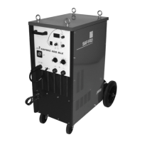
Describes the trolley option for transporting the power source and gas cylinder.